Modelling for analogue and mixed-signal verification
In the semiconductor industry, increase in system complexity and level of integration is driven by technology scaling. As process nodes shrink, system designers can fit more analogue and digital circuits onto the same die, to the point where the entire system is implemented within a single integrated circuit, commonly referred to as System on Chip (SoC).
Author: Igor Ikodinovic, HDL Design House
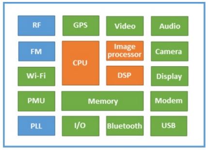
Integration reduces cost and increases overall system capabilities, which stimulates SoC market growth. In turn, new opportunities in consumer, mobile, networking, automotive, medical, imaging, security and other application domains are continually pushing vendors to provide their products with new communication, sensory, power-control, and other analogue-driven features. As a result, modern SoC designs have a significant portion of Analogue and Mixed-Signal (AMS) content, in addition to large digital footprint (Figure 1). While digital design verification tools and methodologies are well positioned to support this growth, verification of AMS IP and SoCs as mixed-signal designs, represents a challenge.
Figure 1. Increasing complexity of mixed-signal designs in modern SoCs
Challenges of analogue and mixed-signal verification
Growing complexity presents a problem for verification at both the AMS IP block level and system level. Functional verification of AMS IP blocks is becoming more difficult because complexity and number of instances of analogue circuits, as well as size of digital control logic within individual AMS blocks increases. In addition, interaction between AMS and digital IP blocks within the SoC is becoming more convoluted. Multiple AMS and digital blocks are often a part of the same functional path, making their operation difficult to validate at module level alone; thereby number of scenarios that need to be exercised upon SoC integration, at system level, grows too.
One of the main issues with analogue and mixed-signal verification is that simulations of AMS designs are slow. Device-level models and respective simulators that are used in analogue design, like SPICE and Spectre, provide highest level of accuracy, but cannot meet the requirements with respect to simulation performance. As an example, a 300ms long SPICE simulation of a PLL can last several weeks. For this reason, even module level verification of AMS IP blocks is often reduced to simulating only a few basic test cases. SoC verification, which implies simulations of the entire system with a multitude of AMS blocks, is virtually impossible with such models.
Another issue is integration of analogue design (as a schematic or analogue netlist) and digital design (in the form of RTL code or gate-level netlist) into a single representation of the system, and running simulations with both analogue and digital signal types simultaneously. Analogue design naturally lends itself to continuous-time simulation, while digital design naturally lends itself to discrete-time simulation, which means that the simulation tool for mixed-signal design and verification needs to support both.
Modeling as a solution
It is rarely needed for an AMS design to be represented at device level using SPICE models. In SoC verification it is often sufficient to use a representation that models only the block’s fundamental behaviour. As an illustration, a PLL model for SoC verification might only consist of a simple periodic signal driver conditioned by presence of power and control signals. Such a model may be many orders of magnitude faster than the SPICE model, yet sufficiently accurate for connectivity checking. Similarly, AMS models for module-level verification, while typically much more accurate than SoC models, do not need to be as accurate as SPICE models either, and may still be hundreds or thousands of times faster to simulate.
AMS circuit models are typically written in Verilog-A, Verilog-AMS, VHDL-AMS, or SystemVerilog language. Verilog-AMS and VHDL-AMS are behavioral modeling languages derived from Verilog and VHDL languages for digital design in order to support analogue and mixed-signal modeling; Verilog-A is just a subset of Verilog-AMS for defining analogue-only systems. SystemVerilog, originally developed as a language for digital design and verification, has also been recently extended to support analogue and mixed-signal behavioral modeling using Real Number Modeling (RNM) paradigm.
Modeling approaches
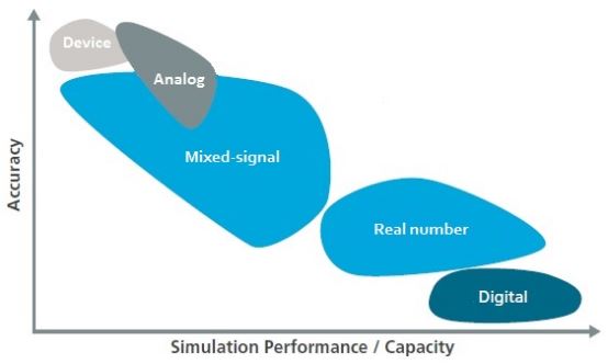
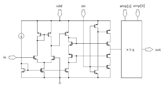
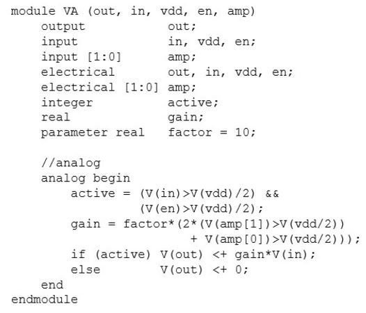
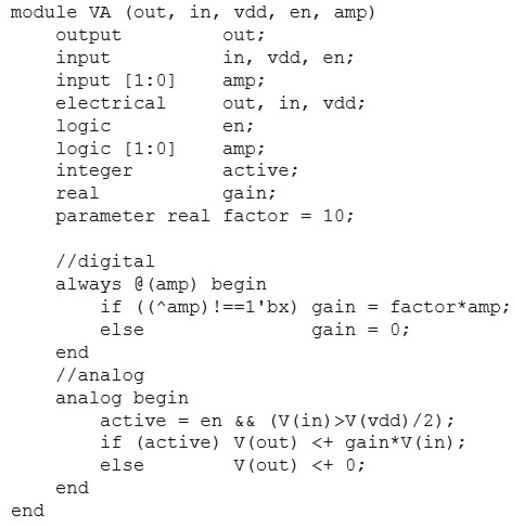
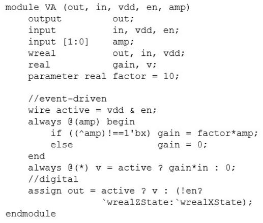
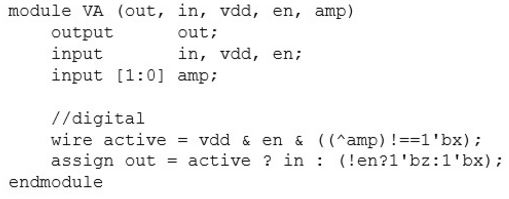
There are five modeling approaches used to represent AMS designs (Figure 2). Each approach has different properties with respect to accuracy and speed (Figure 3). To enable better optimisation, some modeling languages support multiple approaches, even within the same model. Figure 4 illustrates the five model types using a simple Voltage Amplifier (VA) circuit as an example.
Figure 2. Types of modeling
Figure 3. Model accuracy vs performance
Device-level model is the closest representation of an electronic circuit to its physical implementation achievable. The design is represented in the form of a schematic or netlist with design elements modeled as physical devices.
Analogue model defines continuous-time equations that represent voltage and/or current relationships in the circuit at a level that is typically higher than device level. Model equations are solved by the analogue solver during simulation. The solver is invoked in small pre-defined intervals to calculate signal value changes over time.
Mixed-signal model allows simultaneous description of analogue portions of the design using continuous-time modeling constructs and logic portions of the design using discrete-time modeling constructs. The simulator must support and coordinate work of both continuous-time and discrete-time simulation engines to properly simulate interactions between the corresponding parts of the design.
Real number model defines analogue input and output signals using real number values. It is based on the signal flow paradigm, which, along with discretisation of real values, enables simulation using discrete-time engine to achieve close to digital simulation performance.
Digital model defines data flow from input to output strictly in terms of logic (binary) values. This is the same paradigm used in digital design. Analogue operation can thus be modeled only in the context of signals that have a value of logic 0 (signal not present) or logic 1 (signal present).
I
a) Device model (SPICE)
b) Analogue model (Verilog-A)
c) Mixed-signal model (Verilog-AMS)
d) Real-number model (Verilog-AMS/wreal)
e) Digital model (Verilog)
Figure 4. Examples of various model types
Model accuracy and performance
Continuous-time models are usually more accurate than discrete-time models. Continuous-time models capture relationships in the system without relying on any particular order of signal flow from input to output. Each signal can have instantaneous effect on any other part of the system; if the design contains strong feedback, for example, the model will be able to accurately represent it .Discrete-time models, on the other hand, capture functionality using signal flow paradigm; systems with strong feedback, for example, cannot be directly modeled with high accuracy.
Discrete-time simulations are typically faster than continuous-time simulations. Continuous-time simulators invoke slow analogue solvers that calculate solutions of a set of equations which describe the system using matrix-based numerical analysis techniques. Discrete-time simulators, on the other hand, propagate signal values by sequentially triggering events each time output values are calculated from known input values for different parts of the circuit.
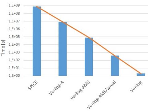
As an illustration, simulation performance of various model types of the same PLL has been given in Figure 5. The time in the chart represents simulation time required to simulate approximately 300ms of real time operation.
Figure 5. Simulation performance of PLL models
Application to verification
The two most important things when it comes to AMS modeling are: 1) understand the design being modeled to ensure the model will properly represent it, and 2) understand verification requirements to be able to determine the required accuracy and modeling approach to be used. In practice, there is sometimes a disconnect between analogue modeling and verification teams, which can lead to using models that are either 'too accurate' and slow, or fast but inaccurate. The former can happen, for example, if models are written by analogue designers who may see that task as 'necessary evil', and don’t have enough modeling skills or time to optimise the models, while the latter can happen if models are written by engineers who do not understand the design well enough due to lack of communication with designers or poor documentation.
Device-level modeling is almost exclusively used during analogue IP development, where all physical effects must be taken into account to ensure that the design will work within a given range of parameter tolerances. Even when run without parasitic extraction, device-level simulations are orders of magnitude below the required module-level and SoC verification performance threshold.
Analogue modeling can be used for debugging during IP development to replace parts of analogue hierarchy whose functionality is relatively easy to capture, in order to speed up simulations. Analogue simulations are usually too slow for use in IP and SoC verification.
Mixed-signal modeling can be used in functional verification of small AMS IP blocks. Analogue parts of the model provide required accuracy, while digital parts of the model provide speed and functionality for controlling operation of the analogue portion of the design. Mixed-signal models, however, are usually still too slow for use in SoC verification.
Real number modeling can be used anywhere where level of abstraction is high enough that bi-directional and feedback interactions that characterise analogue designs can be disregarded. This is, for example, the case with larger analogue IP blocks, such as RF receiver or PLL, and their subcomponents. Due to speed of discrete-time simulations, such models can be used in both IP and SoC verification. For example, a simpler monolithic AMS model can be developed for use in SoC verification, while a more complex hierarchical model can be developed for IP verification and debugging.
Digital models of AMS IP blocks are typically used to check signal connectivity in SoCs. Surprisingly, a lot of problems at the SoC level are not associated with AMS IP basic functionality, but with errors such as wrong signal polarity, mixed up signal lines, using wrong power domains, and similar that digital models can be successfully used to detect. More sophisticated digital models for SoC verification can also include timing.
In practice, rather than creating models using a single modeling approach, it is more optimal to develop models that represent a mix of modeling approaches for various parts of the design. For example, a mix of SystemVerilog/RNM and digital modeling may be well suited for creating monolithic AMS IP models for SoC verification, while more complex hierarchical Verilog-AMS/wreal models may be suitable for IP verification regressions.
In general, by trading model accuracy for simulation speed where needed, it is possible to create a model suited for any given application. In that sense, while there is a tendency to use the same model for different verification needs, it is better to develop models for individual verification applications. This may require additional resources initially, but will result in improved quality and productivity due to an improved verification flow, better time to market, and reduced overall cost due to fewer re-spins caused by sub-optimal verification.

