It’s a function of the junction
As the lifetime of LED lighting fixtures is a function of the LED junction temperature, the desire for compact lighting designs further emphasises the importance of thermal management. By Bernd Pflaum, Principal Engineer, Concept and Development, Linear and Switch mode LED Drivers, Infineon Technologies and Hakan Yilmazer, Head of Technical Marketing, Lighting Application, Infineon Technologies.
System manufacturers are addressing thermal challenges by designing LED systems with appropriate heat sinks, high thermal conductivity enclosures and other advanced thermal design techniques. Generally, manufacturers do not consider the LED driver IC as a control component in the thermal system, but the use of an LED driver IC with intelligent over temperature protection could provide an additional control mechanism that can increase the lifetime of LED light sources significantly, ensuring the rated lifetime and reducing the incidence of defective products.
Depending on the lighting manufacturer and application, useful lifetime for LED lighting products range from approximately 20,000 hours to more than 50,000 hours compared to less than 2,000 hours for incandescent bulbs.

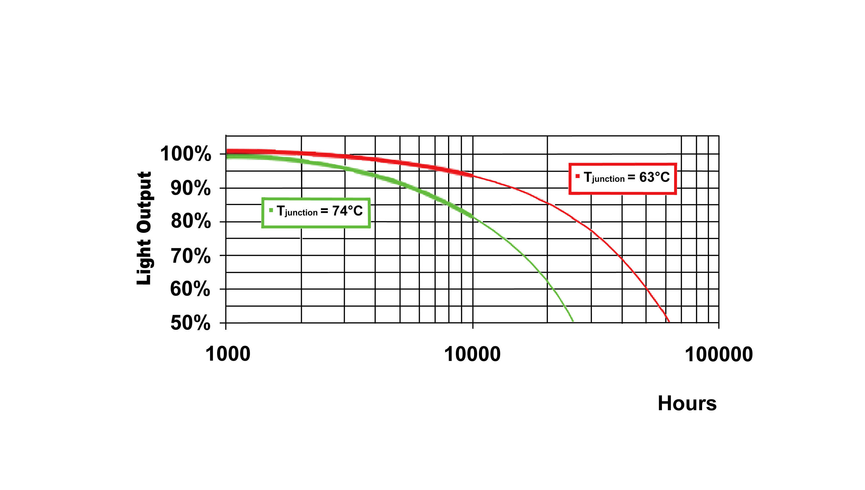
Figure 1: The lifetime of LEDs is a function of the junction temperature (Source: EOS)
The lifetime of LEDs is directly related to the junction temperature to which they are exposed, increasing temperatures can reduce the operating lifetime significantly. Figure 1 illustrates the light output over time (experimental data to 10,000 hours and extrapolation beyond) for two identical LEDs driven at the same current but with an 11K difference in Tj. Estimated useful life (defined as 70% lumen maintenance) decreased from about 37,000 hours to 16,000 hours, a 57% reduction by a temperature increase of only 11K.
Different approaches for thermal protection
Temperature protection with LED driver ICs can be implemented in a variety of ways. Some LED driver devices include a sense pin to which an external temperature sensor may be attached. Different temperature sensing devices, including diodes, on-chip sensors, positive temperature coefficient (PTC) or negative temperature coefficient (NTC) thermistors can be used in LED lighting applications to protect the LEDs from overheating. NTC thermistors are often the preferred choice for temperature sensing and control in many of these applications, primarily because of their small package sizes and attractive price/performance ratio. But accuracy, response time and thermal gradient depend on the way the NTC thermistor is mounted. Once the temperature is accurately sensed, the response to overtemperature must be considered.
The typical response is to trigger an abrupt turn off of the current to the LEDs when a critical temperature has been detected. These devices then ‘restart’ when the temperature is reduced, or wait until a power cycle to restart. There are some disadvantages related to these methods:
The abrupt shut-down method leads to setting the shut-down at a very high temperature in order to avoid incorrectly triggered shutdown. While this high value usually protects from catastrophic failures it can result in significant reduction in the lifetime of the LEDs.
Turning off the LED current means that the light is switched off abruptly. This can cause a serious situation like panic in public areas.
Most drivers automatically restart when the system has cooled; once restarted the system will heat up and shut-down can occur again resulting in a disturbing flicker effect.
Drivers that latch ‘off’ after the failure can require a power on reset, which is often difficult or even impossible.
In security relevant applications (e.g. the illumination of emergency exits, escape routes, emergency shut-down switches, etc.) a simple shut-down of the LED driver is insufficient, as maintaining illumination is essential. This shut down behaviour may also be insufficient in non-security related applications where light output is necessary under extreme conditions, such as hot environments.
Smart protection
Infineon Technologies has a granted patent describing a power supply unit for LED current control, which includes a temperature sensor and trigger circuit that provides temperature dependent LED output current, to protect the LEDs from overheating.

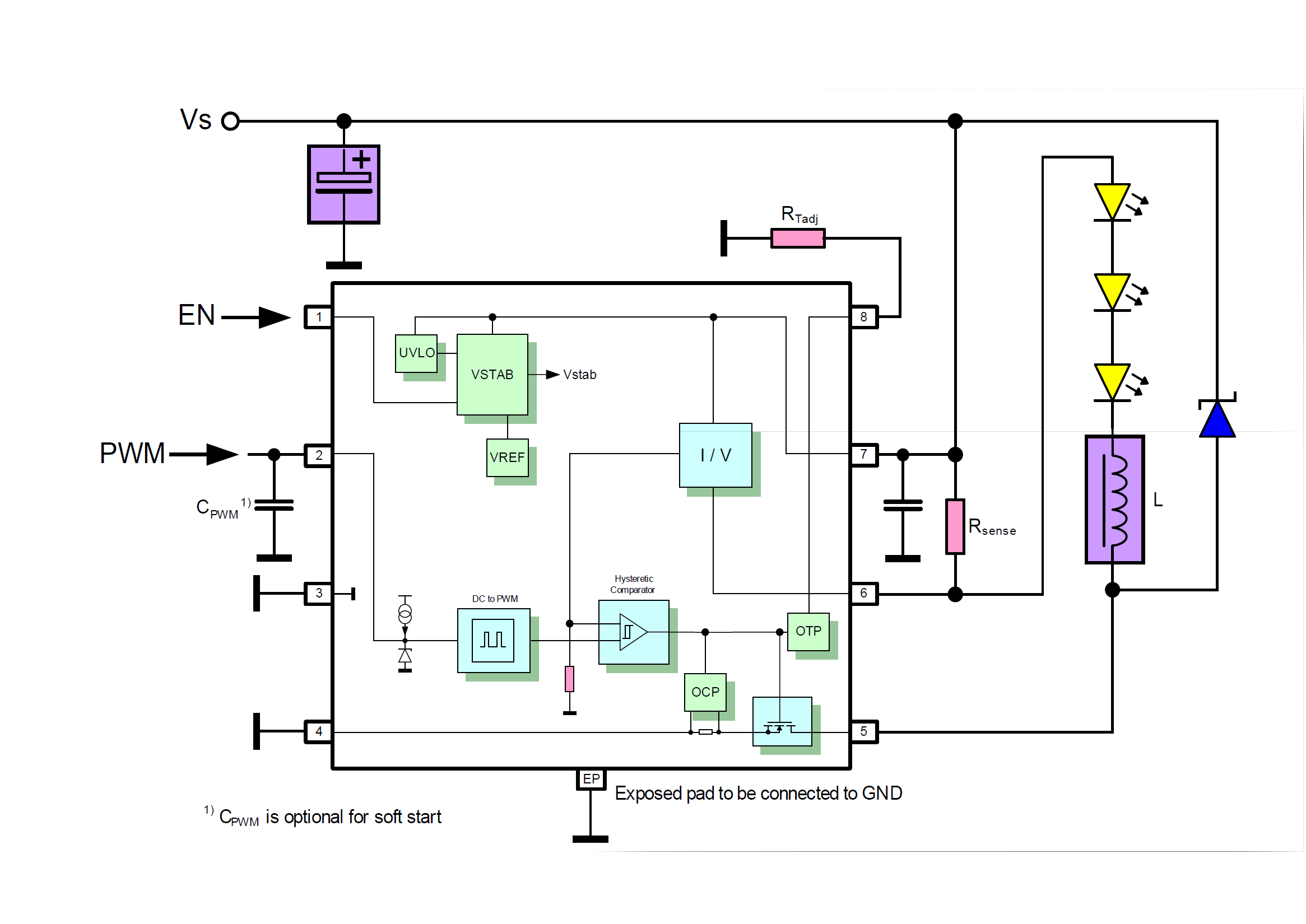
Figure 2: Application circuit with the new ILD6070 driver. The current reduction is triggered at a threshold of the solder point temperature of the LED driver IC, which is adjustable using an external resistor connected to the Tadj pin
Leveraging the key idea of the above mentioned patent, the LED driver IC can be used as a thermal sensor. A patent pending technology protects the LEDs with a slope dimming characteristic and adjustable trigger temperature, to overcome the limitations of conventional LED system designs. The new technology was implemented in the ILD6150 and ILD6070 DC/DC hysteretic buck LED driver with high side current sensing (Figure 2).
In addition to saving system costs (no NTC needed) the implementation of the specific smart temperature protection provides some additional benefits to LED system integrators.
Reducing the LED average current with an integrated slope dimming mechanism protects the lifetime of the LEDs by reducing their junction temperature. The protection circuit should ideally result in LED power delivery that has a smooth protection characteristic, avoiding hard switching which may lead to flickering.
If a light source driven by the new LED drivers is exposed to a higher temperature condition than foreseen in the thermal design, the driver ICs will reduce the average current of the LED continuously in a slope dimming characteristic, not abruptly.
This continuous range of adjustment allows the system to come to an equilibrium point that provides continued operation of the light source under exposure to the extraordinary condition with reduced light output. If the thermal equilibrium is overrun by additional thermal load this gradual reduction continues until a minimum of 25% of the target LED average current is reached and the light source will continue to provide light output with a luminance level of minimum 25% of the target light output.

Figure 3: Simplified block diagram of the smart over temperature protection circuit
The patent pending circuit design is based on standard components like resistors, diodes, capacitors, transistors, comparators or operational amplifiers (Figure 3). The temperature measurement is handled using serial SI diodes placed near the power stages, as the hottest and most sensitive parts in the driver IC. If LEDs are heating up, the power stages would recognise the temperature difference. The diodes are also placed close to power stages to protect the IC itself from overheating.
Maintaining light
Dimming by generating an internal PWM signal during thermal protection ensures that the light colour doesn’t change. Since the light colour remains practically unchanged it might not be visible to end users that the LED system is in thermal protection mode.
The LED current will be modulated by changing the duty cycle of an internally generated 1.6kHz PWM signal, as a result the output light generated by the LED will be modulated by the PWM pulses, too. The key advantage of having PWM modulated light output is that the wavelength spectrum and therefore the colour of the light remained unchanged.
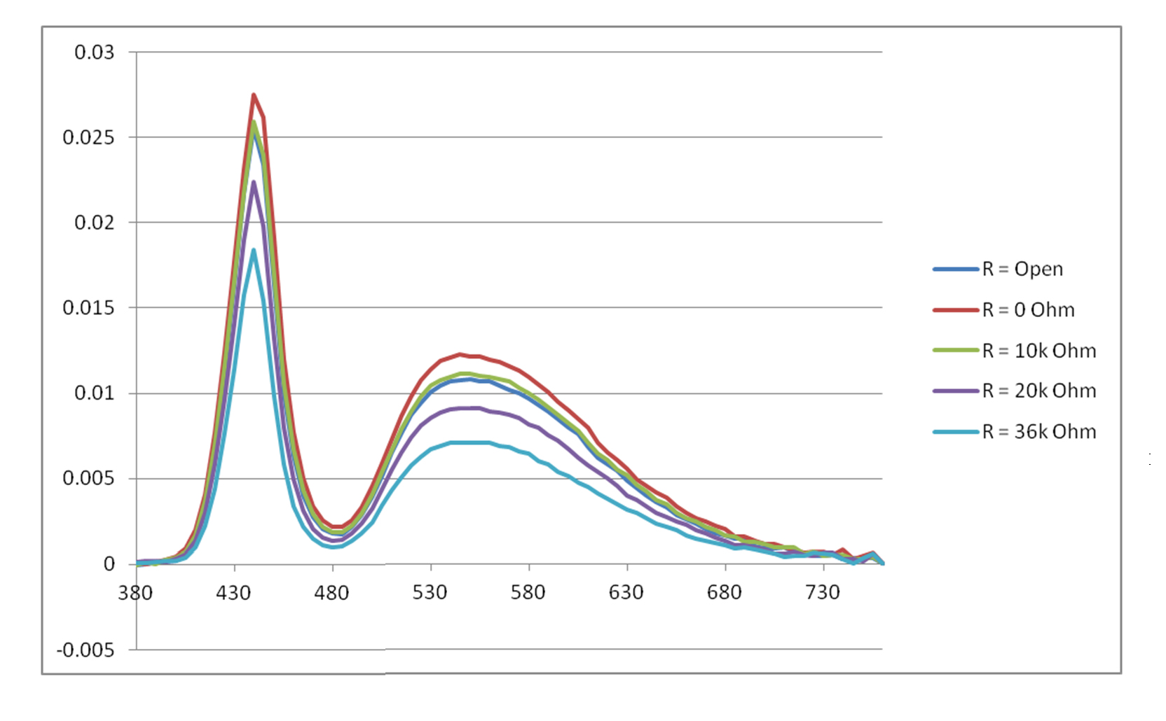
As shown in Figure 4, the wavelength spectrum is only reduced in magnitude at different settings on the adjustable external resistance. For this experimental setup the module has been heated up by LEDs and the hot ambient air to 120°C, where the IC works at thermal protection mode.

Figure 4: PWM modulated light output keeps the colour unchanged during thermal protection
With the patent pending smart thermal management technology described here and used in the latest LED driver generation, the lifetime and cost of LED designs can be significantly improved. This results in various benefits for luminary manufacturers and end users.


