Watching the detectives - developing fashionable wearables
Wearable electronics, such as medical devices and fitness trackers, are going through a period of rapid change. The revolution in ‘personal electronic devices’ is improving the ability of individuals and healthcare professionals to monitor and manage their health. Graeme Clark, Principle Engineer, Renesas Electronics, explains.
The miniaturisation of what was previously large monitoring and diagnostic equipment means that we can now wear many of these devices as we go about our everyday lives, providing users with regular and reliable information about a wide range of physical parameters.
The best place for many of these technologies to be worn is on the wrist, replacing the centuries old analogue watch with a smarter electronic device.
However, many of the patients who would benefit most from the growth of these technologies are amongst the younger or older members of society. Often, they cannot afford or are afraid of smart products that operate at the cutting edge of technology. They often struggle to use the technology or, quite often for some medical devices, don’t like the ‘look and feel’ of the product.
Wouldn’t it be ideal, then, to develop future medical devices in a form factor that would be easy to understand in these markets. They could offer the look and feel of an analogue or hybrid watch, while providing the features necessary to support many medical sensor applications.
Above: Table 1. Typical parameters for 2-wire and 3-wire stepper motors
To address this issue, Renesas has used the new ultra-low power Silicon on Thin Buried Oxide (SOTB) process to develop the new R7F0E017 Embedded Controller. This device offers extremely low power operation, the SOTB process offering power consumption in the range of 20µA/MHz in normal operation and standby mode current of less than 150nA, as well as specific features aimed at this application. See Figure 1 for the feature set of the R7F0E017. These devices have been designed to operate both on batteries and on energy harvested from the environment, forming the basis of a new generation of products.
The R7F0E017 has several unique features designed specifically to support applications providing the functionality of a digital or analogue watch. The most important of these is the dedicated timer for the watch hand motor driver, which is designed to control the second, minute and hour hands of a wide variety of different watch movements (the mechanical elements, such as the gearing and hands of a watch), while consuming a minimal amount of energy.
This timer is designed to operate in the lowest power states of the microcontroller with a self-power of less than 3nA. This article will look in more detail how we can use the timer for the watch hand motor driver to drive the hands of an analogue watch.
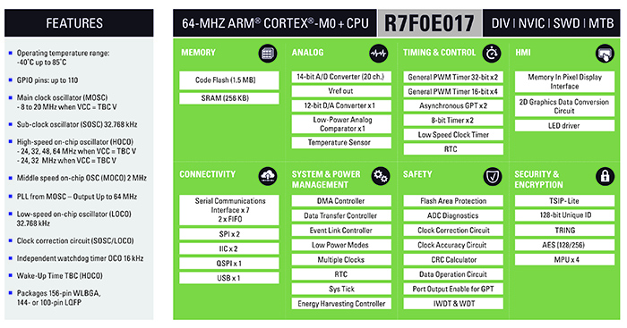
Above: Figure 1. The R7F0E017 feature set
Today, most watch movements use some combination of 2-wire stepper motor and 3-wire stepper motors to control each of the watch hands. In a typical movement, each stepper motor can be connected directly to the motor terminal of the R7F0E017 motor drive timer, and up to three stepper motors can be moved. Up to three 2-wire (2-signal control) stepper motors can be connected simultaneously to the device, and up to two 3-wire stepper motors can be connected simultaneously. A combination of one 2-wire stepper motor and two 3-wire stepper motors is also possible, enabling the support of a range of different movements.
Two-wire and three-wire control offers the user a trade-off between power consumption and rotational speed. The typical parameters of each type of stepper motor are shown in Table 1.
The stepper motor’s rotor rotates 180° with one pulse. If the hand of the watch has a one second advancing gear configuration, 100 pulses in one second of forward rotation means that the hand of the watch (the second hand) advances for 100 seconds in one second.
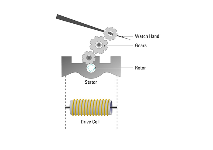
Above: Figure 2. Structural drawing of a 2-wire watch motor. This is just an example, and the exact configuration can vary
Assuming that the second hand is driven by a 2-wire stepper motor and the minute hand is driven by a 3-wire stepper motor, one forward pulse, the second hand of 2-wire system moves 6° (= 360°/60). Assuming that the 3-wire minute hand moves six times every ten seconds to turn one minute, it moves 1° (=360°/60/6) with one forward rotation pulse.
Figure 2 shows the structure of a simple watch motor. The stepper motor for this example consists of a rotor, a stator, and a drive coil. The drive coil consists of a winding and a core. The rotor is made of permanent magnets. The core of the drive coil and the stator are made of high magnetic permeability material because they need to pass a magnetic field. Electrical pulses to control the motor are supplied by two wires, each connected to opposite ends of the drive coil. For this reason, the stepper motor shown in Figure 2 is called a 2-wire stepper motor.
The simple 2-wire motor relies on simple magnetism to generate rotation. One magnet is provided by the rotor and the other is an electromagnet formed by current passing through the drive coil, the force generated between these causing the rotor to rotate.
There are two rotating directions in the 2-wire stepper motor, forward and backwards. In the forward direction, the rotation is easy to initiate as the energy to generate the rotation is small and the motor can operate with simple electrical pulses.
Forward rotation is used for the most frequent needle movements, as it can reduce current consumption. Usually, it is used when the needle turns clockwise through several gears from the rotor of the motor. Note that even if the needle is turning clockwise, due to the gear configuration from the motor’s rotor it does not necessarily mean that the watch hand is turning in the same direction.
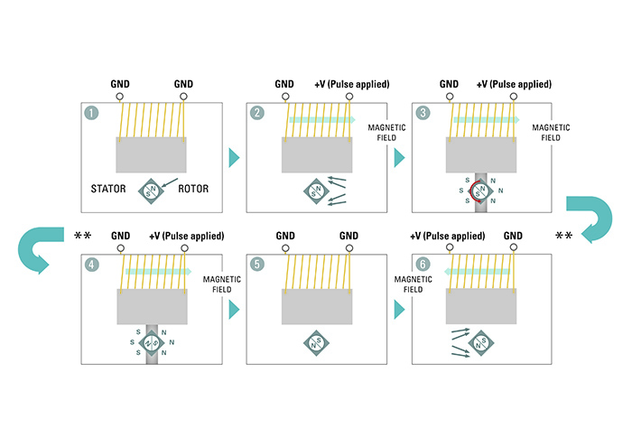
Above: Figure 3. Diagram showing forward rotation
In its initial state, with no current supplied to the drive coil, the motor is stable and the rotor is located at a position where the boundary between the N pole and the S pole is inclined with respect to the stator, as shown by j in Figure 3. This position is called a magnetically stable point. The central part of the N pole and the S pole of the rotor with the strongest magnetic force is closest to the stator due to the shape of the hole in the stator in which the rotor sits. If the hole in the stator has a circular shape with the same centre as the rotor, no matter which direction the rotor is facing, it becomes equivalent. However, if the stator has a non-uniform shape, the distance from the central axis of the rotor to the stator differs. The central part of the N pole and the S pole of the rotor faces the stator at the point where the distance is shortest. The boundary between the N pole and the S pole of the rotor faces the point where the distance is longest. The shape of the stator in which the rotor shown in j in Figure 3 is rectangular, but this is just an example – it is usually circular with notches used to provide the required non-uniformity.
As a next step, we can apply an electrical pulse to the drive coil as shown in k in Figure 3. Current flows in the drive coil, and at this time a magnetic field is generated in the direction based on Ampere’s law. The magnetic field has the property of being transmitted through a material with higher magnetic permeability than air, so it is transmitted through the stator and returns to the drive coil again. At this time, there is only a portion at which the width of the stator is extremely narrow where the rotor is resting, and the magnetic field is concentrated in this region. However, at this stage, there is no magnetic force acting as a motive force to turn the rotor.
After applying a voltage to the drive coil, the current flowing to the drive coil increases over time. In areas where the width of the stator is extremely narrow, the magnetic field saturates and the permeability decreases, and becomes the same as the permeability of air. As a result, the portion with the grey shadow on the stator l in Figure 3 becomes magnetically separated and functions as a magnet. That is, as shown in l in Figure 3, N and S poles occur on the left and right of the grey shadow. The N pole of the rotor attracts the S pole of the stator, and the S pole of the rotor attracts the N pole of the stator. Since the magnets of the rotor and the different poles of the magnets formed on the stator try to face each other at a small rotation angle, the rotor is shown in the direction indicated by the red arrow in l in Figure 3 will rotate. This produces the state shown in m in Figure 3. In this state, if the voltage applied to the drive coil is turned off, the magnetic stability point will be reached with a small rotation angle, resulting in the state of n in Figure 3. Thus, with one electrical pulse, the rotor rotates 180 degrees. As described above, the constant angle of rotation with one electric pulse is 180 degrees, and the step angle is 180 degrees.
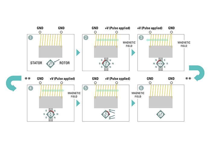
Above: Figure 4. Diagram showing reverse rotation
Furthermore, as in o in Figure 3, when an electric pulse is applied in a direction different from k in Figure 3, this produces what has been described in k to n in Figure 3. The rotor further rotates 180 degrees in the same direction as k to n in Figure 3 and returns to the state of j in Figure 3. In this way, the rotor makes one complete rotation.
To turn the motor in the reverse or counter clockwise direction is slightly more difficult, as the reverse direction is the direction in which the stepping motor does not easily rotate. Reverse rotation is normally only used in special cases for watch hand rotation, as it consumes more current than forward rotation so we will not discuss this in detail here. However, the required method is shown in Figure 4.
The watch hand motor drive circuit in the R7F0E017 is specifically designed to create the necessary waveforms to drive these coils, both in the case of forward and reverse directions and also for both 2- and 3- wire systems. It is optimised to automatically operate the motors with the lowest possible current consumption. A simplified diagram of this is shown in Figure 5.
The motor drive circuit is designed to supply constant voltage to the coil, and is therefore ideal to work both with batteries and with applications that use energy harvesting. These include the use of photovoltaic cells or thermoelectric generators.
The watch hand motor drive circuit provides the pulse generation function to generate the waveforms required to rotate the rotor. It also provides the output control functions required both to initialise and to provide for continuous operation of each hand of the watch.
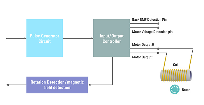
Above: Figure 5. Simplified stepper motor drive circuit
The motor drive also includes important functions to detect the presence of an external magnetic field and to provide feedback about the rotation of the motor. The magnetic field detection function is capable of detecting the back electromotive force generated when placed within in an AC magnetic field, such as near electric blankets / carpets, microwave ovens, CRT TVs, etc. The presence of such a field could cause the motors to stop or operate incorrectly, so this function allows the detection and management of such a situation. The rotation detection function detects the back electromotive force generated when the hand moves and can be used to reduce power consumption during this operation.
In the R7F0E017, the clock system can be derived from an external 32kHz crystal and uses a special clock correction circuit to create both a 2kHz and a one second clock, both accurate to better than two parts per million. These clocks are then used to drive the stepper motor driver extremely accurately.
The introduction of the watch hand motor timer onto such a powerful microcontroller, allows the development of a powerful new generation of wearable applications, while maintaining the look and feel of a product that most people are very comfortable with - the humble analogue watch. The R7F0E017 will allow developers to integrate their applications into a physical format that users are comfortable with and will be able to wear with confidence.
The R7F0E017 is available now in sample quantities with mass production targeted for the end of 2019.


