Charging towards fewer cables
Wireless charging provides a convenient way for users to charge all their mobile devices simultaneously, as a result deployment is growing. By David Zelkha, Managing Director, Luso Electronics
There is nothing new about the concept of inductive charging, also known as wireless charging. Electric toothbrush users have been familiar with it for many years; but the proliferation of smartphones and tablets, and the associated difficulties with the various charging connectors involved, more companies are taking an interest in the idea.
The physics of wireless charging is straightforward; power is transferred between two coils using inductive coupling. The charging unit contains one of the coils that acts as the transmitter and the receiver coil is in the unit to be charged. An alternating current in the transmitting coil generates a magnetic field which induces a voltage in the receiving coil, and that voltage can be used to power a mobile device or charge a battery.
Palm was one of the pioneers of wireless charging for mobile phones using what were, at the time, innovative coil sets from E&E Magnetic Products (EEMP) and just a few years ago the problem of charging these devices, with their energy sapping WiFi and Bluetooth features, was widespread with almost every phone having a different connector. The advent of mini-USB, used by many of the mobile phone makers, has eased this problem somewhat but the convenience of wireless charging is attracting growing attention.
However, its use has been held back due to a couple of factors. One was the lack of a standard, but that has been solved, more of which later. And the other related problem was unwillingness by most phone makers to install the necessary coil in a device that is already crammed with electronics. Some companies introduced sleeves that could be put over the phone but that in a way lost the convenience of just being able to drop the phone on a charging mat.

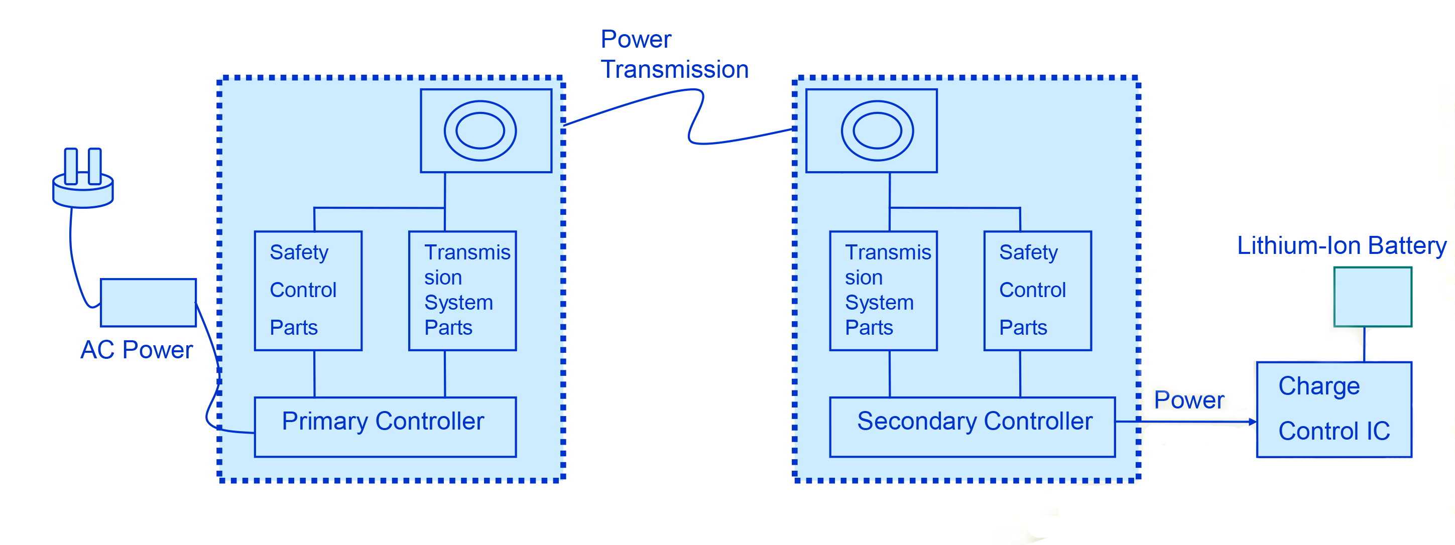
Figure 1 - Basic overview of wireless charging technology
A change in the market happened in 2009. Before that, the reluctance to put the coil into the phone was understandable given that it wasn’t just the coil but a number of other components that went with it. But this altered when Texas Instruments introduced the first chipset for this. It was followed soon by IDT and now there are five or six companies – such as NXP, Freescale, Panasonic, Active-Semi and Toshiba – making chipsets, and this has helped drive interest from the phone makers.
Leading the charge
Some car makers are also looking at this technology to provide drivers and passengers with an easy way to charge their devices while in the car. Toyota has already brought out models with this installed. The 2013 Toyota Avalon limited edition was the first car in the world to offer wireless charging based on the Qi standard. The in-console wireless charging for Qi–enabled devices was part of a technology package that included dynamic radar cruise control, automatic high beams and a pre-collision system.
The Avalon’s wireless charging pad was integrated into the lid situated in the vehicle’s centre console. The system can be enabled by a switch beneath the lid, and charging is as simple as placing the phone on the lid’s high-friction surface. Cadillac has announced that it will have wireless charging in the 2015 model of the ATS sport sedan and coupe. It will also add the technology to the CTS sports sedan in autumn 2014 and the Escalade SUV at the end of 2014. Mercedes Benz has adopted the Qi standard for its wireless charging plans. Most other car makers are also looking at the technology. And aftermarket charging mats that can be fitted in most vehicles are available from numerous suppliers.
Once a large number of vehicles have this installed, then it is another driver to the phone manufacturers as it shows there is an available market and that this is a desirable feature. Also, once phone users experience the convenience of wireless charging in their car, they are likely to drive demand for this to be available at home and in the workplace as well.
The main limitation on wireless charging is the short distance needed between the transmit and receive coils, which must be close enough to ensure a good coupling. The technology works by creating an alternating magnetic field and converting that flux into a current in the receiver coil. However, only part of that flux reaches the receiver coil and the greater the distance the smaller the part.
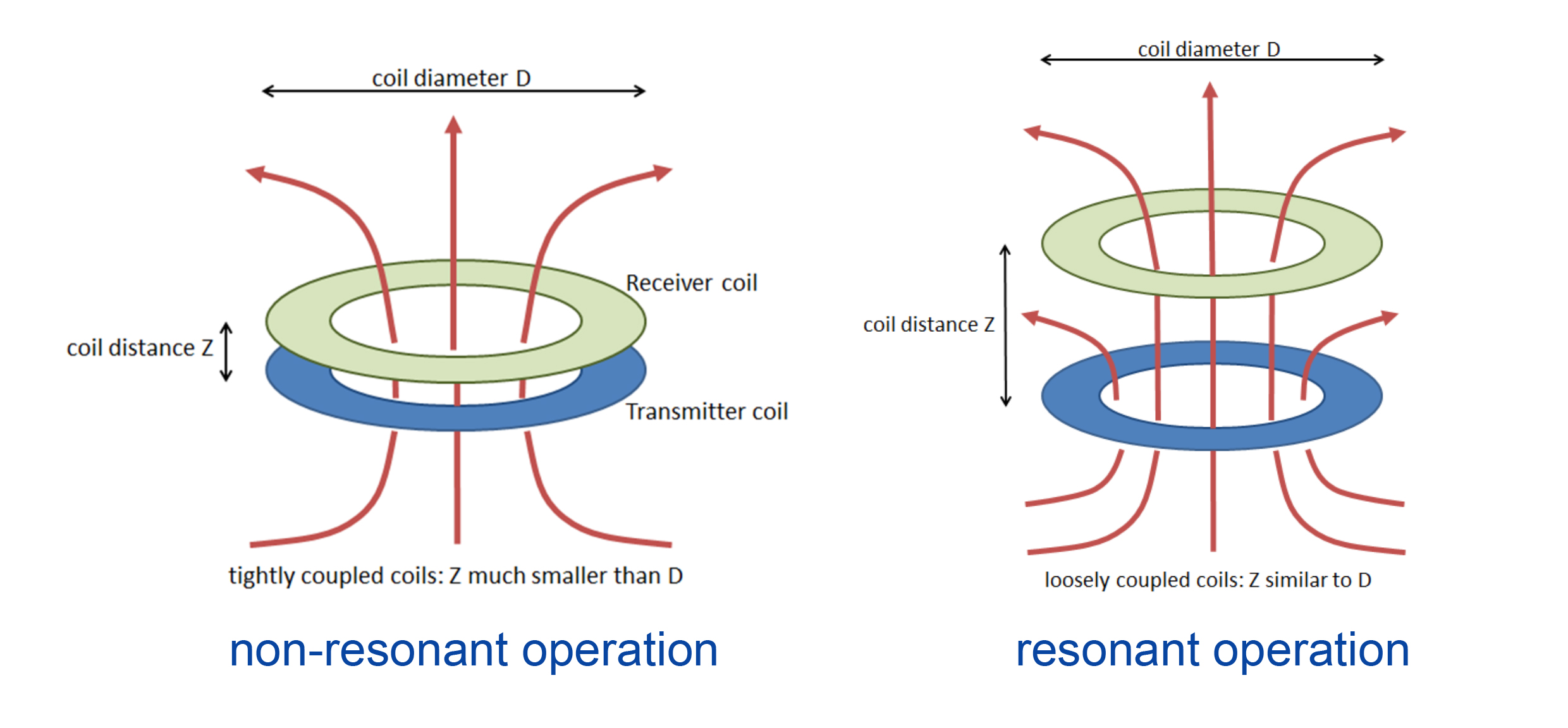
The higher the coupling factor the better the transfer efficiency. There are also lower losses and less heating with a high coupling factor. When a large distance between the two coils necessary it is referred to as a loosely coupled system, which has the disadvantages of less efficiency and higher electromagnetic emissions, making in unsuitable for some applications.
A tightly coupled system is where the transmit and receive coils are the same size and the distance between the coils is much less than the diameter of the coils. Given that people are used to using charging cables that seem to get shorter with each new phone, this is not seen as a major issue. Charging time is roughly the same as with a traditional plug-in charger. Also, as most of the charging is done by placing the phone directly on a mat that contains the charger, there is no significant distance involved.
Standards
There are three main standards covering inductive charging, with the basis of all three being the same. The Alliance for Wireless Power (A4WP) standard has a higher switching frequency, which allows a greater charging distance. The Power Matters Alliance (PMA) Powermat standard also covers the alternative resonant charging method. There is talk that these two standards could soon be merged into one.
But WPC (Wireless Power Consortium) is the oldest and the most adopted standard in the market, with some 1200 different products in the market. The consortium has more than 200 members and its standard is known as Qi (pronounced ‘chee’), which specifies the whole charging circuit on the transmit and receive side and how it should be implemented in the charging devices.

Figure 2 - The difference between resonant and non-resonant operation
Most Qi transmitters use tight coupling between the coils and operate the transmitter at a frequency that is slightly different from the resonance frequency. Even though resonance can improve power transfer efficiency, especially for loosely coupled coils, two tightly coupled coils cannot both be in resonance at the same time. The Qi standard therefore uses off-resonance operation because this gives the highest amount of power at the best efficiency. However, there are Qi-Approved transmitters that will operate at longer distances, loosely coupled and at resonance.
This shows that Qi is an evolving standard. As new applications and requirements come along, the WPC is adding to the standard to keep it up to date. For example, the original standard had just one transmit coil and one receive coil. This was then extended to three transit coils to give a greater area on which a device being charged could be placed. And some now have even more coils; the standard already covers up to five. This makes it easier for users dropping the phone onto the mat, as they no longer have to position it carefully. Tightly coupled coils are sensitive to misalignment, but a multi-coil mat can be used to charge more than one device at the same time.
This is seen as one of the big advantages of wireless charging; users need just one mat onto which they can put all their phones, tablets and cameras and have them charged simultaneously. As well as for home or office use, this adds convenience for those who travel and are regularly staying at hotels - only one charger needs to be packed. There is also now a number of charging areas in public places. These have been installed in airports in Asia and the USA. Japan has more than 3300 public locations where consumers can charge their devices wirelessly. And even the French Open tennis tournament had Qi chargers in the guest areas.
There is an environmental benefit as well. The current system sees many corded chargers thrown away each time users upgrade to new mobile devices. A wireless mat that complies with the relevant standard can carry on being used with the new device if it too complies. And multi-coil transmitters allow the power to scale with increasing power levels by powering more coils underneath the receiver. The first smart phones needed 3W, whereas today’s devices require over 7.5W and this is growing. Tablets, e-book readers and ultrabooks need from 10 to 30W. A loosely coupled system can achieve multi-device charging with a single transmitter coil, provided it is much larger than the receiver coils and provided the receivers can tune themselves independently to the frequency of the single transmitter coil.
In the early days, there were also problems if, say, a coin from the user’s pocket was pulled out at the same time as the phone and sat between the phone and the mat. The mat would then try to charge the coin instead. The standard was thus changed to bring in what was called foreign object detection so that the likes of coins and keys are recognised and not charged. Another problem that was sorted early on was the fear that the switching frequency could interfere with some automotive applications such as remote door opening. If a phone maker wanted a new design, then the WPC is willing to work with the company to adapt the standard to suit so the manufacturer can still use the Qi logo on the device. Compare this with A4WP, which only covers single coil, loosely coupled resonant systems.
Design-in
The main components are the chipset, the transmit and receive coils, and some passives. All the available chipsets meet the WPC standards even though packaging and pin-outs may be different. Texas Instruments and IDT are the main players in the North American market and NXP is the largest player in Europe. There are multiple suppliers for the coils, of which EEMP was the first.

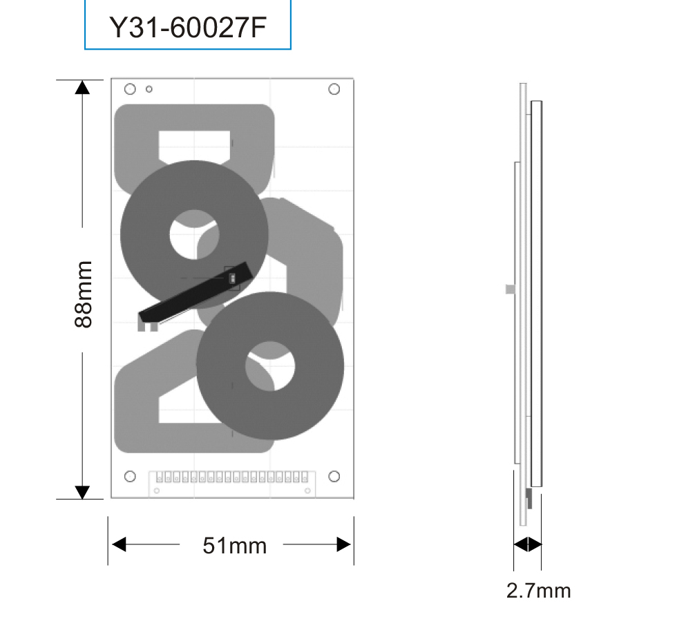
Figure 3 - Multi-coil systems can use different shapes to increase the charging area, as can be seen with this configuration from EEMP
Most of the research and development work is in customising these products, as there tends to be an even split in the market between standard products and customised versions. Some phone makers, for example, want really thin receive coils to keep the size of the phone down. This can cause problems as the ferrite used tends to be brittle, but EEMP has made a flexible ferrite to get round this. This makes it easier to deploy where there is a curved surface rather than moulding a standard ferrite into the correct shape. The moulded ferrite route is also more expensive.
EEMP, which is a member of the three main standard bodies - WPC, A4WP and PMA - has transmitter and receiver coil standard modules plus units that can be tailored to the size, thickness and shape needed by the application. These are available from Luso Electronics, which can provide samples and have small batch quantities available to support prototype and lower volume builds. They comply with the Qi standard and the two ranges provide 5W and the 15W extension to the Qi standard. Available in various operating temperature ranges, they are RoHS compliant, halogen free and provide low resistance and low temperature rise when operating.
The push now is to develop clever and novel techniques to expand the available market for this technology beyond smartphones and the like. Such applications could include audio systems, torches, LED candles, test equipment, handheld instruments and PoS equipment. The potential market is expanding, demonstrating the flexibility of the technology. More and more phone makers are adopting the Qi standard for wireless charging and most now have at least some models in their range that are capable of this. As car manufacturers start to introduce wireless charging in their vehicles, an increasing number of consumers will experience the convenience and start looking for this as a desirable feature when they choose their next smart phone. The result should be a growing market for this technology.


