Verifying compliance of USB 2.0 interfaces
As the USB interface remains, by far, the most dominant interface in mobile devices, electronic consumer goods and industrial products, demand for reliable, fast test solutions in development and integration is equally high. Guido Schulze, Head of Product Management, Oscilloscopes, with Rohde & Schwarz in Munich, discusses further in this article from ES Design magazine.
In high-speed (HS) mode, the USB 2.0 interface achieves a data transfer rate of 480Mbit/s, and in the PC world (where the interface originated), the 5Gbit/s USB3.0 standard has already become established (super-speed mode). For many mobile applications, PC peripheral devices, equipment and systems used in industry, medicine and A&D environments, the data rate provided by the USB 2.0 interface is fully adequate, which explains its growing popularity in these sectors.
The USB 2.0 standard was published in 2000, and commercially available components based on this standard have now reached technical maturity. Nevertheless, developers are still faced with challenges related to the integration of these components on printed boards and in devices. For example, insufficient isolation with respect to other boards can result in ground loops or crosstalk, which can have a negative impact on the operation of the USB interface. For debugging and stability tests, developers must rely on test solutions that conform to the relevant standards. Accordingly, the organisation responsible for USB standardisation — the USB Implementers Forum (USB-IF) — has defined a test process with appropriate compliance measurements whose purpose is to ensure the error-free interoperability of a wide variety of devices with USB interfaces. Products bearing the USB logo must pass this compliance test, and so developers need automated USB test solutions in order to prepare for compliance testing performed by certified test labs.
Automated compliance
The high measurement accuracy of the R&S RTO oscilloscopes provides a solid foundation for reliable compliance test results. For testing USB 2.0 interfaces in HS mode, either the RTO1024 oscilloscope (2GHz bandwidth) or the RTO1044 (4GHz) can be used. ScopeSuite is a powerful software tool from Rohde & Schwarz that guides the user step-by-step through compliance tests, configures the oscilloscope, automatically executes the measurements and compiles the results in a clear measurement report. The R&S RTO-K21 software option includes USB 2.0 compliance tests for USB devices, hubs and hosts.
To connect the device under test (DUT) to the oscilloscope, Rohde & Schwarz offers the R&S RT-ZF1 test fixture set that can be used for USB 2.0 signal quality tests and for legacy tests on USB 1.1 and USB 1.0 interfaces.
 test.png)
Figure 1: Test setup for HS device signal quality (SQ) test
The test setup varies based on whether the DUT is a USB device, host or hub and on the speed mode selected for compliance testing. The test fixture boards (signal quality board and load board) contain different sections for the individual tests. Figure 1 shows the test setup for HS device signal quality (SQ) tests. R&S ScopeSuite runs on a PC that controls the the oscilloscope, which is connected to the DUT via a differential probe and the test fixture board. The USB-IF software (HS electrical test tool) sets the DUT to the necessary test state. This software should be run on a separate PC since it modifies the USB stack during operation.

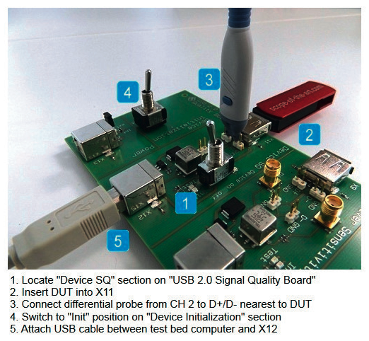
Figure 2: Picture-based instructions for the test sequence: device HS mode, signal quality test with the RT-ZF1 test fixture set
ScopeSuite controls the measurement settings and test sequence on the oscilloscope via the LAN interface. Prior to starting the test, the user can define user data, all settings for the test setup and measurement reports. The limit editor allows the user to individually adjust the standard-specific test limits. Taking the test setup into account, the software guides the user through all of the selected compliance tests. Detailed instructions with pictures make it easy to correctly connect the probes to the test fixture and DUT (Figure 2).
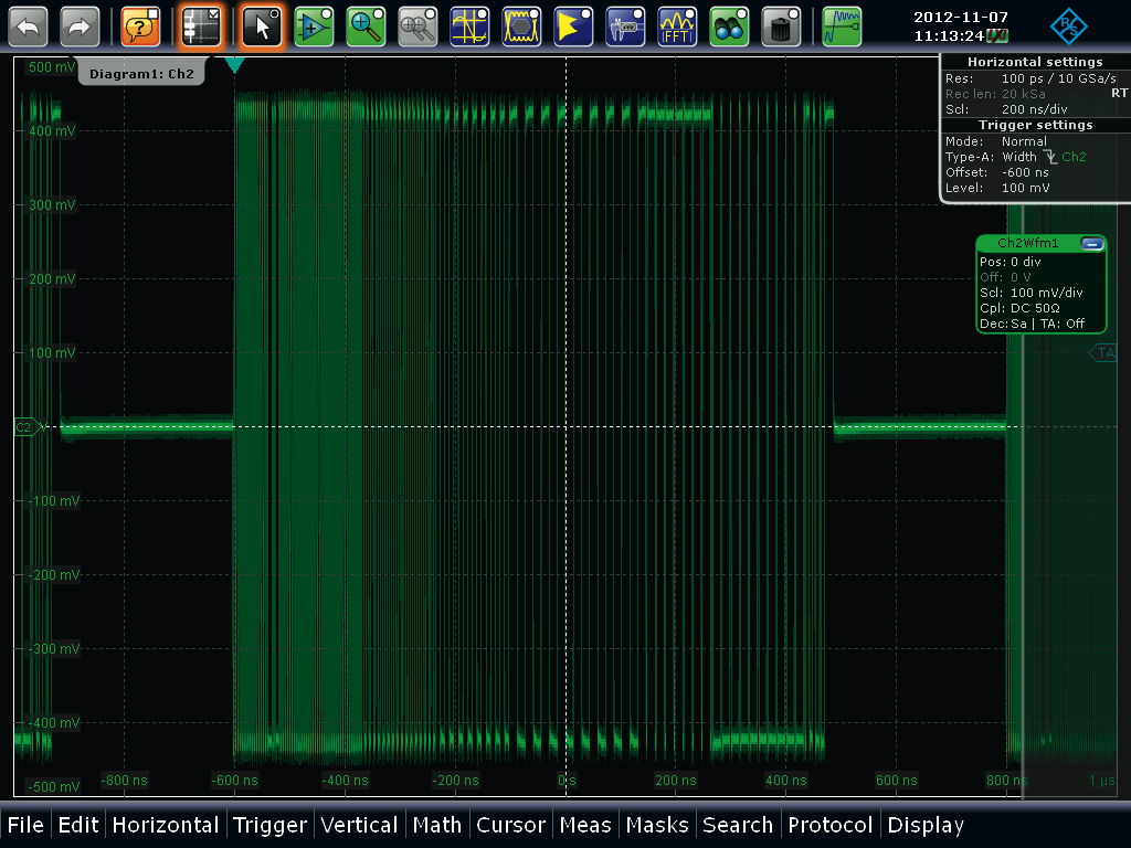
At the beginning of a typical test, the HS electrical test tool configures the test mode for the DUT. The DUT then transmits specific test signals that are captured by the oscilloscope (Figure 3) and passed on to the software for analysis, using the USB-IF electrical test tool to analyse the results.

Figure 3: Waveform during HS signal quality test
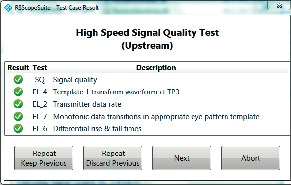
Test sequences are very flexible with ScopeSuite. For example, the user can use the Repeat – Keep Previous function (Figure 4) to repeat test cases as required for debugging or stability tests. All results are documented in the measurement report. If the user makes an error during the test, such as an improperly connected probe or a test mode that was incorrectly configured with the HS electrical test tool, the result can simply be discarded and the test case repeated using the Repeat – Discard Previous function.

Figure 4: Flexible control of test sequence
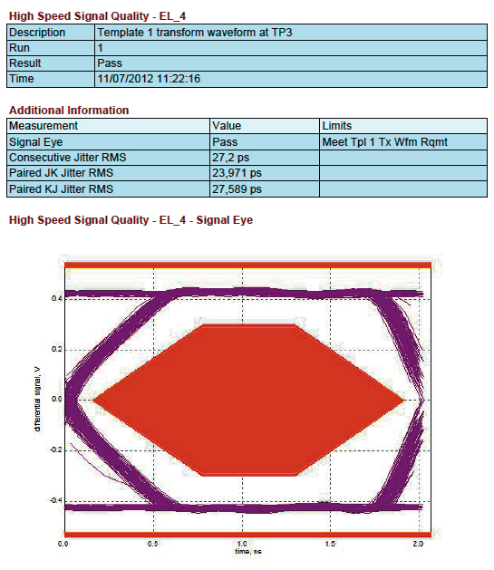
Detailed documentation of measurement results is not only an essential component of compliance testing, it is also very important for debugging and exchanging data with colleagues and customers. ScopeSuite offers an extensive range of documentation functions. The user can, for example, add measurement details and screenshots to the pass/fail results. The software also allows new tests to be added to an interrupted test sequence so that all results will be available in a single report (Figure 5). Reports can also be generated at a later point in time and distributed in various formats including PDF, RTF and HTML.

Figure 5: Reports can be individually configured: numerical results and diagram of the eye pattern test


