Optocouplers for insulation resistance measurement
Andy Poh, Application Development Manager, Thomas Sng and Chun Keong Tee, Product Marketing Engineers, Broadcom, highlight the importance of effective insulation resistance measurement.
In high voltage applications like industrial motor, solar energy generation, Electric Vehicle (EV) Battery Management System (BMS), the measurement of insulation resistance is critical to determine if the system can be put in operation without serious safety concern. Under high voltage condition, failure of insulation will cause high leakage current, damaging the system and injuring the user.
Insulation resistance will need to be measured periodically as it will degrade overtime by high voltage electric and thermal stress. As such, it is important that the system is installed with an insulation resistance measurement function to monitor any degradation and take remedy actions before failure occurs. This paper will discuss how optocouplers can provide high voltage isolation and complete the insulation resistance measurement function in the system.
Principle of operation
To determine the insulation resistance, a direct voltage of more than 500V is first applied to the system. For industrial motor, IEEE Std 43-200 provides the guidelines of the DC voltage as shown in Table 1.
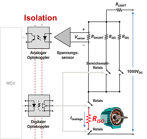
The voltage, VSENSE is then sensed across a shunt, RSHUNT to determine the leakage current, ILEAKAGE. The insulation resistance, RISO of the motor windings to the frame can then be calculated by Ohm’s law as shown in Figure 1. RSEL resistor network is used to select and cover the entire range of the insulation resistance.
Using the same IEEE standard as reference, a general rule-of-thumb for good insulation resistance is above 10Mohm.
For solar energy generation, DIN EN 61646, DIN IEC 61215 and DIN VDE 0126-1-1 specify the standard for PV modules and inverters respectively.
PV modules (DIN EN 61646, DIN IEC 61215) : RISO > 40MΩm2.
PV Inverters (DIN VDE 0126-1-1) : RISO > 1kΩ/V, 500kΩ minimum.
As high voltage (>500V) is applied during insulation resistance measurement, galvanic isolation is required to separate and protect the low voltage microcontroller (MCU) and the user handling the equipment. Although, the isolation and insulation resistance measurement can be completed by simple analogue and digital isolators with discrete voltage sensors and switches, Broadcom has a wide portfolio of optocouplers with integrated functions to provide a compact and easy to use solution.
Optocouplers for insulation resistance measurement
Broadcom optocouplers have been used extensively in high voltage industrial and automotive applications like the inverters in motor drives and traction in electric vehicles. One of the reasons is optocouplers can provide reinforced galvanic isolation certified by safety regulatory IEC/EN/DIN, UL and CSA. The other reason is it has high Common Mode Transient Immunity (CMTI) to maintain signal integrity in noisy industrial and automotive environments.
The ASSR-601J and ASSR-601JV/JT are photovoltaic MOSFET solid-state relays for industrial and automotive 125ºC applications. The ASSR-601J consists of a LED input stage optically coupled to switch two discrete high voltage MOSFETs with breakdown voltage of above 1,500V. The isolation between the LED input and MOSFET output is also certified by IEC 60747-5-5 with a working voltage of 1414VPEAK. The MOSFET breakdown voltage and input to output isolation voltage make the ASSR-601J well suited for insulation resistance test voltage of up to 1,000V.

Table 1. Guidelines for DC voltages to be applied during insulation resistance test
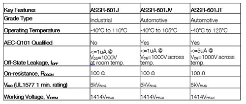
At an applied insulation resistance test voltage of 1,000V the ASSR-601J has a leakage current of less than 1µA when in off state. This translates to an off state resistance of 1GΩ, two orders higher than a ‘good’ insulation resistance of 10Mohm, making it a suitable switch for insulation resistance measurement. ASSR-601J has very low on state resistance of 100Ω, which will not affect the accuracy of the measurement and a maximum allowable load current of 50mA. This is usually more than sufficient than the application typical of less than 10mA.
For high temperature application like BMS in EV, the automotive grade ASSR-601JV has a guaranteed off-state leakage current of less than 1µA (up to105ºC) and ASSR-601JT of less than 5µA( up to 125ºC). The off-state high resistance property is critical because insulation resistance degrades as temperature increases. IEEE Std 43 states that the insulation resistance is halved for every 10ºC increase in temperature. In other words, insulation resistance measured at room temperature has to be reduced by the temperature correction factor when operating at high temperature. But it should be noted that, the ASSR-601JV and ASSR-601JT unique off-state leakage current property at high temperature will not affect the insulation resistance measurement regardless of operation temperature conditions.

Table 2. Recommended insulation resistance value
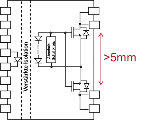
The package of the ASSR-601J is specially designed to meet functional isolation requirement and reduces the possibility of arcing over the output pins when high voltage is applied. The ASSR-601J is equivalent to 1FormA Electromechanical Relays (EMR) in a 300mm 16-pin SOIC package.
This package ensures more than 5mm of creepage between the drain pins of the MOSFETs at the output pins. Functional insulation requires 1mm creepage distance for every 200V of applied voltage. This package will allow insulation resistance test voltage of up to 1,000V.
The ACPL-C87B and ACPL-C87BT voltage sensors are optical isolation amplifiers designed specifically for voltage sensing in industrial and automotive 125ºC applications. It is certified by IEC 60747-5-5 with a working voltage of 1414VPEAK, making them well suited for insulation resistance test voltage of up to 1,000V.

Figure 1. Block diagram of insulation resistance measurement circuit
ACPL-C87B/C87BT has ±0.5% gain tolerance, excellent linearity, wide 2V input range and most importantly, high 1GΩ input impedance, suitable for isolated voltage sensing across shunt. It should be noted that the shunt resistor, RSHUNT, has a low resistance of typically 2kΩ. In a parallel connection, the input impedance of the voltage sensor will affect the accuracy or will need to be compensated. With the high 1GΩ input impedance, which is six orders higher than the shunt, it has negligible impact (less than 0.001%) on the overall shunt resistance, and hence the accuracy of the shunt voltage.

Table 3. Industrial and automotive grade ASSR-601J specifications comparison
Summary
The measurement of insulation resistance is critical to determine high voltage system reliability and safety. Broadcom has a wide portfolio of optocouplers with integrated functions suitable for insulation resistance measurements. Here, the ACPL-C87B/C87BT and ASSR-601J/JV/JT are used to demonstrate how to meet isolation requirements and perform voltage measurement and relay switching to complete and simplify the design of insulation resistance measurement in a 1,000V system.

Figure 3. ASSR-601J in a 16-pin SOIC package with more than 5mm creepage between output pins
For higher test voltage above 2,000V, the same voltage sensor, ACNT-H87B is also available in a 15mm creepage package with a working voltage of 2262VPEAK. Digital optocoupler, ACNT-H60L/H51L are also available in 2262VPEAK and can be used to control the relays. The ASSR-601J can then be connected in series to complete of insulation resistance measurement for a 2,000V system.


