
EMI debugging with oscilloscopes using fast FFT
Oscilloscopes with advanced FFT capabilities and high sensitivity and dynamic range are the ideal instruments for electromagnetic interference (EMI) debugging. MXO oscilloscopes from Rohde & Schwarz with their fast performance let design engineers swiftly and accurately detect and analyse EMI emanating from electronic circuits and boards with time-correlated RF analysis.
This article originally appeared in the June'24 magazine issue of Electronic Specifier Design – see ES's Magazine Archives for more featured publications.
EMI/EMC regulations help ensure reliable operation and safety for users of electrical and electronic equipment, and designers need to invest significant time to keep their products within these limits.
During the design and prototyping phases, it is common practice to perform debugging measurements that identify and resolve potential EMI/EMC challenges before subjecting the product to compliance testing. This proactive approach significantly mitigates the risk of noncompliance. The goal is to efficiently locate emission sources that might impact conformity results using a range of testing tools and troubleshooting techniques. For an all-encompassing solution that streamlines the debugging process, an oscilloscope with time-correlated RF measurement capabilities, such as the MXO oscilloscopes from Rohde & Schwarz, should be considered.
These oscilloscopes, for example, provide a synchronised display of analog signal characteristics, digital timing, bus transactions and the frequency spectrum. This is enabled by the instruments’ ASICs, which process RF measurements in the hardware and overcome traditional limitations of slow FFT computation. The user interface with familiar spectrum analysis controls (center frequency, span and RBW) helps in addition. It allows users to independently optimise the displays in the time and frequency domains. The instruments offer a high spectrum display update rate. Signals can be displayed in both a waveform and spectrum view, without splitting the signal path. Designers can easily and accurately correlate time and frequency events with the instruments’ RF and time trigger functions. Peak list and log-log scales help with easy EMI comparison.
RF performance matters for EMI debugging
Oscilloscopes with a high dynamic range and input sensitivity of 500 µV/div at full measurement bandwidth like the MXO series allow to detect even weak emissions. The 12-bit ADC and 18-bit HD mode enhance the vertical precision. The hardware-accelerated FFT makes analysis in the frequency domain fast and responsive thanks to the high acquisition rate and functions such as colour coding of the spectral display depending on the frequency of occurrence.
Additional features supporting EMI debugging
- Ultrafast FFT analysis: > 45000 FFT/s update rate helps capture spurious and elusive spectral events
- Logarithmic display and dBµV scales: easy comparison with EMC test lab results and checking with limit lines based on CISPR standards
- Fast results with automatic peak list measurement: automatically measure frequency peaks marked in the FFT and listed in a table
- Max./min. hold and average trace: statistical traces record the maximum, minimum and average value of spectral energy
Gated FFT: correlation between frequency and time
Tools like a gated FFT function enable FFT analysis on a user-defined region of the acquired time domain signal. Users can move this time window across the signal to determine which segments of the time domain signal correlate to which events in the spectrum. This way, they can, for example, correlate unwanted emissions from switched-mode power supplies with overshoots from the switching transistor.
Probe set for E and H near field measurements
For conducted emissions, line impedance stabilisation networks (LISN) typically include noise output for measurements. However, this includes all the conductive noise in the device under test (DUT). To locate the emission sources within the DUT, near field probes are useful to detect magnetic and electric fields in closer proximity. Oscilloscope vendors offer different probes to complement their instruments: The R&S HZ-15 near field probes, for example, offers a frequency range from 30MHz to 3GHz. The R&S HZ-16 amplifier extend the lower frequency down to 9kHz. A near field probe set includes various electrically shielded probe tips with special shapes that are designed for different measurements.
Why are fast FFTs important?
While all modern oscilloscopes support FFTs as a means of providing spectral information about the waveform, the required computation often slows down the acquisition rate. Most oscilloscopes can be as slow as 1 FFT/s to 100 FFT/s. This means that the instrument will have a longer blind time, missing important spectral events between acquisitions. This can be frustrating when locating spectral emissions with near field probes, since the user needs to hold out the probes for several seconds to detect possible noise.
Rohde & Schwarz has implemented powerful ASICs in the MXO oscilloscopes which allow a hardware implementation of FFT processing. This enables ultrafast calculations that provide more than 45000 FFT/s. The blind time is minimised and the responsiveness simplifies sniffing for emissions with near field probes. Users can simply scan the DUT with the probe to determine where and when the noise could be an issue.
Where to start?
To identify the source of an EMI issue, first developers need to determine the source of energy and find out how this energy is being radiated. Common sources of EMI problems include:
- LCD emissions
- Ground impedance
- Component parasitics
- Poor cable shielding
- Power supply filters
- Switching power supplies (DC/DC converters)
- Internal coupling issues
- Inadequate signal returns
- ESD in metalised enclosures
As a first step, developers need to locate the source of the energy, using an H near field probe. It’s important to align the probe to determine the direction of the magnetic flux through the plane of the loop. By moving the H near field probe around the conductor, the energy source can be located. Then, with help of a finer probe, the search can be concentrated on a smaller area.
Examining the coincidence of EMI problems with electrical events is arguably the most time-consuming process in EMI diagnostics. A fast FFT makes correlating the spectral and time events easy. MXO 5 series oscilloscopes provide multiple FFTs that can have their own RF settings, enabling further debugging by comparing spectral events at different DUT locations.
Summary
EMI can be elusive and a failure to comply with EMC standards can hinder product development. EMI debugging early on in development can help detect problems at an early stage and improve circuit performance.
Rohde & Schwarz offers with the MXO oscilloscopes valuable tools for developers to perform EMI debugging on electronic circuits, featuring powerful FFT signal processing, high input sensitivity and extensive acquisition and analysis capabilities. The oscilloscopes' hardware-accelerated FFTs and colour-coded spectral display provide an overview of the frequency of occurrence of spectral components in the acquired signals, allowing fast identification of EMI sources. Since the FFT function is controlled in a similar way as it is in spectrum analysers, users can easily navigate in the frequency domain without having to worry about the time domain settings.

Featured products
MAX17793
Analog Devices Inc.

3V to 80V, 3A, High-Efficiency, Synchronous Step-Down DC-DC Converter
| SKU: | MAX17793 |
|---|---|
| Stock: | 9316 |
| Cost: | $3.64 |
MAX22516
Analog Devices Inc.
IO-Link Data Link Controller with Transceiver and Integrated DC-DC
| SKU: | MAX22516 |
|---|---|
| Stock: | 8000 |
| Cost: | $5.42 |
Product Spotlight
102991834
BeagleBoard

Single Board Computer (SBC), BeagleY-AI
AM67A BeagleY-AI Jacinto 7 AR...
| SKU: | 2820-102991834-ND |
|---|---|
| Stock: | 208 |
| Cost: | $56.24 |
SC1110
Raspberry Pi
Raspberry Pi 5 2GB
The Raspberry Pi 5 2GB model represents a leap for...
| SKU: | 2648-SC1110-ND |
|---|---|
| Stock: | 0 |
| Cost: | $38.33 |
AKX00069
Arduino
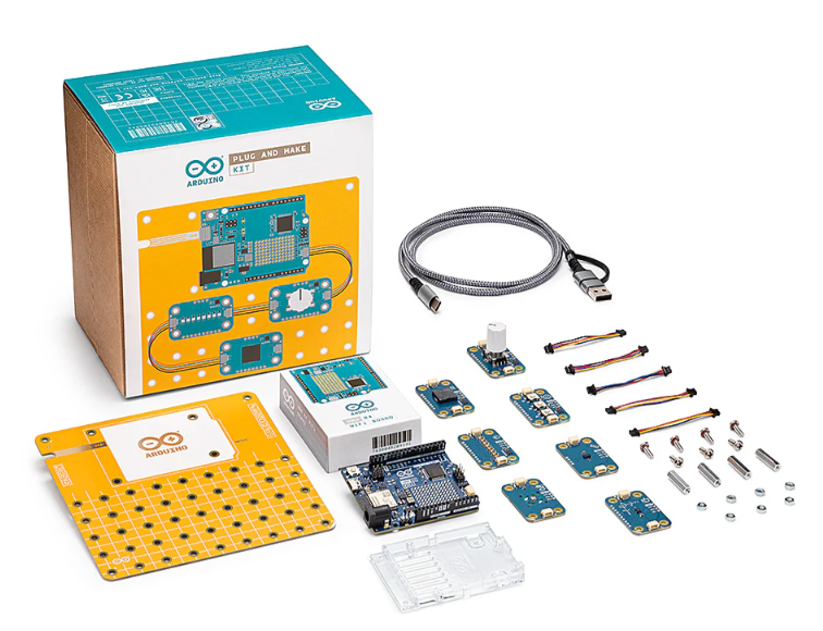
Arduino Plug and Make Kit
The Arduino Plug and Make Kit features the ...
| SKU: | |
|---|---|
| Stock: | 968 |
| Cost: | $66.97 |
300361-0011
Molex
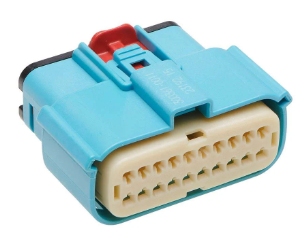
MX150 Mid-Voltage MatSealed Female Connector Assembly, Dual Row, 20 Circ...
| SKU: | |
|---|---|
| Stock: | 280 |
| Cost: | $2.51 |