
Have you got the jitters?
Ensuring valid data transfer with GDDR5 data jitter characterisation on a high bandwidth oscilloscope. By Ai Lee Kuan, OPD Memory Product Manager with Agilent.
The GDDR5 (Graphics Double Data Rate, version 5) dynamic random-access graphics card memory technology is used in high performance GPU (Graphics Processing Unit) for the mainstream mobile and gaming users. Latest GDDR5 technology offers data rates of 5Gbit/s or higher. At these high data rates, data jitter measurements are important in order to understand the effects of jitter on the data valid window. Measuring and understanding the components of jitter can enable designers to minimise jitter on the overall system design to ensure valid and accurate data transfer. Read and write data should be analysed separately for their individual data valid windows. With GDDR5's design of a free running data clock (WCK), small unit intervals, and minimal distinguishable skew between read and write data to WCK, identification of read and write data to make the data jitter measurement can be difficult and time consuming. High bandwidth oscilloscopes or mixed signal oscilloscopes are the two most common devices used to perform the data jitter measurement.
Impact of jitter
The GDDR5 SGRAM transfers data using free running differential forwarded clock (WCK/WCK#) with both input and output data registered and driven respectively at both edges of the forwarded WCK for read and write training. Read and write training allows for data timing and amplitude level margin optimisation. While not specified in the JEDEC specification, jitter characterisation is considered an important measurement task when operating at these high data rates. Sources of jitter from the GDDR5 system such as inter-symbol interference (ISI), cross talk and duty cycle distortion (DCD) limit the performance of the graphic cards and the interface between the memory controller and the DRAM.
Jitter is defined as the deviation of a signal transition from its ideal time. As data rates increase, timing budgets decrease and each pico second of margin gained becomes more important. At high data rates, even a small amount of jitter can easily close the data valid window of the read and write data; this will ultimately increase bit error rate (BER) and data sampling error.

Figure 1: GDDR5 write data eye diagram representing the impact of DJ and RJ on the data valid window
When operating at date rates of 5Gbit/s or higher, the data valid window is very small. The noise in the system or crosstalk from adjacent electrical signals or even electromagnetic interference could easily distort the signal integrity, resulting in data sampling error. A real time eye diagram provides eye height and eye width measurement for checking signal integrity, and an estimate of the data valid window. However, simply measuring a data eye with real time eye diagram measurement does not give a full insight into the valid data window and expectations of a bit failure rate. Figure 1 shows a write data eye with one million unit intervals (UI) measured. This initial measurement of one million UI would result in a data input value window of 200ps. The deterministic jitter (DJ) and random jitter (RJ) lines show the impact of jitter over a long period of time and the actual data input valid window (tDIVW) after 1 trillion UI (a 1e-12 bit error rate or BER). Deterministic jitter is generally bounded and predictable and can be correlated to the data stream; such as inter symbol interference and duty cycle distortion. Random jitter is generally Gaussian and is unbounded. As with any Gaussian distribution, as a population increases, so does the peak to peak value of the distribution. Therefore, total jitter is DJ plus a BER multiplier of RJ. Note that data input valid window is made on write data. You can see how important it is to make jitter BER measurement calculations to form a statistical measurement of total jitter to understand the design's data valid window result and to properly understand at what rate you can expect an error within the design. Additionally, understanding the components and sources of jitter can enable designers to reduce jitter in their designs and ensure more accurate data transfer.
Making measurements
One of the most challenging tasks for GDDR5 system designers is separating read and write data in order to make the jitter measurement. Read and write data share the same data path, however they are separately important to the design. Many designers would use a mixed signal oscilloscope to trigger on the command protocol to get the correspondent read and write data. Using a mixed signal oscilloscope to separate read and write data requires signal accessibility to clock, CS#, RAS#, CAS# and WE# in addition to WCK and DQ. This method is cumbersome because signal accessibility is very limited in tight board spaces and in some cases, the connections to multiple signals may cause serious probe loading issues.

Figure 2: Separate read command with InfiniiScan+ zone qualify trigger tool
Jitter measurements can also be made with a high bandwidth oscilloscope, where the data separation technique involves connecting only CAS#, WE#, WCK, and DQ to the standard 4 analog channels of the oscilloscope to identify the read and write commands. When CAS# toggles low, this identifies any column address command. The command possibilities with this condition are narrowed down to deselect, MRS, Read, Write, Refresh, and self refresh entry. When WE# is low at the same time as CAS#; deselect, MRS, and write are the only remaining possible commands. Write latency can be determined and used to separate write cycles from deselect and MRS. When the device is in deselect, data must be held in the ODT state. For MRS, data outputs for Vendor ID is at 10ns delay from the MRS command; leaving data that is transitioning at the write latency from a CAS# and WE# low to be write data. When WE# is high with a CAS# low transition, this identifies deselect, read, refresh, and self refresh entry. Deselect, refresh, and self refresh entry requires that data to be in the ODT state for these commands. Read can be separated from these commands by identifying transitioning data at the read latency as shown in Figure 2.
Now that write and read data can be identified and separated, jitter can be measured. The data input valid window, tDIVW is the window of valid write data to the respective WCK clock edge. The time interval error (TIE) is measured for each data edge in relation to WCK clock edge. Two TIE trends can be measured; one for data transitions before WCK and another for data transitions after WCK to calculate tDIVW as shown in Figure 3. Once a TIE trend of data is established, jitter decomposition of deterministic jitter and random jitter can be determined. A total jitter for data on each side of WCK can be calculated and a tDIVW is determined for a desired bit error rate. Notice that Deterministic Jitter is different in value between left and right eye. However, Random Jitter values are the same for each.

Figure 3: Before and After WCK clock edge time interval error trend measurement for write data. The left side of the tDIVW can be determined from the midpoint of TIE plus ½ Djdd + QBER*Rj(rms). The right side of the tDIVW can be determined from the midpoint of TIE minus ½ Djdd + QBER*Rj(rms). tDIVW can then be calculated as the window between the two measurements.
True data validity
It is just as important to understand the read data being presented to the controller from the GDDR5 device. Measurements can be made in the same manner for read data so that memory controller designers can understand the impact of jitter on the data being sent from the GDDR5 SGRAM to the memory controller and create design expectations to develop a robust memory controller.
It is important to ensure that these measurements are made with 4 channels of high bandwidth and high sampling rate oscilloscope to ensure that you measure the real edge of the GDDR5 system. Additionally, high performance oscilloscopes with low noise and jitter measurement floors contribute minimum noise to your measurements. You can be confident that you are gaining true depiction of your signal and ultimately a true data valid window measurement of your design and not of your measurement setup or measurement tool. This enables designers to truly measure and debug their designs for optimal performance and gain the most margins with minimum design cycles which ultimately will save significant cost and time.
As GDDR5 technology reaches higher datas rate of 5Gbit/s or higher, the signal amplitude and data valid window becomes very small resulting in increase of data sampling error. Accurate random jitter and deterministic jitter decompositions measurement to compute statistical measurement of data input valid window helps you quantify the data sampling error for margin analysis. Using only 4 channels of high bandwidth oscilloscopes coupled with low noise floor and low jitter performance, such as the Agilent Infiniium Q series high performance oscilloscopes not only provides an easy setup with less signal requirement compared to using a mixed signal oscilloscope but also allows you to successfully separate read and write data to make the jitter measurement, with the confidence that you can achieve the real edge of your signals and gain the most margin out of your GDDR5 system design.

Featured products

MAX17793
Analog Devices Inc.
3V to 80V, 3A, High-Efficiency, Synchronous Step-Down DC-DC Converter
| SKU: | MAX17793 |
|---|---|
| Stock: | 9316 |
| Cost: | $3.64 |
MAX22516
Analog Devices Inc.
IO-Link Data Link Controller with Transceiver and Integrated DC-DC
| SKU: | MAX22516 |
|---|---|
| Stock: | 8000 |
| Cost: | $5.42 |
Product Spotlight
102991834
BeagleBoard

Single Board Computer (SBC), BeagleY-AI
AM67A BeagleY-AI Jacinto 7 AR...
| SKU: | 2820-102991834-ND |
|---|---|
| Stock: | 212 |
| Cost: | $56.24 |
SC1110
Raspberry Pi
Raspberry Pi 5 2GB
The Raspberry Pi 5 2GB model represents a leap for...
| SKU: | 2648-SC1110-ND |
|---|---|
| Stock: | 0 |
| Cost: | $38.33 |
AKX00069
Arduino
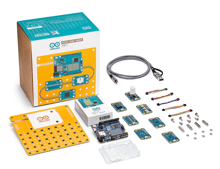
Arduino Plug and Make Kit
The Arduino Plug and Make Kit features the ...
| SKU: | |
|---|---|
| Stock: | 968 |
| Cost: | $66.97 |
300361-0011
Molex
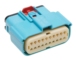
MX150 Mid-Voltage MatSealed Female Connector Assembly, Dual Row, 20 Circ...
| SKU: | |
|---|---|
| Stock: | 280 |
| Cost: | $2.51 |