
Inkjet printed wirebonds for sensor interconnections
Advanced packaging of semiconductor-based sensors brings very specific interconnection requirements.
These often are related to a very narrow pitch of the interconnections or the fragility of the sensor. Different interconnection methods may also be needed because of the orientation of the sensing area or the integration of the sensor in Flexible Hybrid Electronics.
DoMicro has developed an interconnection process for micro assembly of semiconductor-based sensors. This interconnection process is described as inkjet printed wire bonding. This article highlights results from recent work on an application with complex sensors. Furthermore, it includes a perspective on the competitive advantages brought by inkjet printed wirebonds.

Figure 1. Inkjet printed wire bonds for the interconnection of microprocessor bare die
Figure 1 shows a sample with interconnections made with inkjet printed wire bonding. This printing method can be considered as 2.5D printing. Depending on the sensor and integration and processing challenges, the inkjet printed wire bond interconnection method brings advantages over conventional interconnection methods.
Reduced heights: Thin integration of bare die sensors for flexible hybrid electronics can be done for BGA or QFN packages which are soldered to the PCB. These typically are made with wire-bond interconnections from the sensor die to a lead frame. This results in a relative thick package.
Integration of the bare (and thinned) die directly on the flexible circuit reduces the total height. The inkjet printed wirebond interconnection method can be used to interconnect bare dies to the flexible circuit without adding extra height to the package.
Configuration choices: Some optical sensor chips have their contact pads on the same plane as the sensor area. Interconnection with the (Flexible) PCB can therefore not be done using flip chip methods with anisotropic bonding. An advantage with inkjet printed wire bonds is that different configurations are possible.
Solutions for heat limitations: The limitations of the processing conditions of some opto-semiconductor sensors do not allow wire bonding or flip chip bonding. The temperature, pressure, or ultrasonic energy of these interconnection methods can damage those sensors. Inkjet-printed wire bonds uses less harsh processing conditions. This is a non-contact interconnection method where only limited heat is required.
Inkjet printed interconnections enable new (ultra-thin) applications
Using inkjet printing technology, DoMicro has developed a state-of-the-art approach for micro assembly of demonstrators for advanced applications with for example ICs, passive components, sensors, and LEDs. In previous work, DoMicro has worked on the integration of thinned bare dies using the inkjet printed wire bond interconnection method. The technology for integrating dies is one of the key enablers for the realization of new applications in flexible hybrid electronics (FHE), e.g., in in-mould electronics or smart glass.
This approach was developed for a wireless IoT demonstrator with a face-up thinned bare die. The die was interconnected on its bond pads. This demonstrator is shown in Figure 2. As it is impossible to inkjet print conductive tracks via a steep vertical surface, a dedicated ramp structure guides and supports the inkjet-printed silver conductors. This innovative approach of contacting avoids any regular and height consuming wire bond loops with glob top or as applied in advanced packaging, a redefinition layer or substrate (RDL) interface. The ‘die first’ approach is creating minimal height for assembling and mounting dies in systems. It is very suitable for sensor ICs for which the active side should be face up and it offers a compatibility of material surface interaction.
The wireless IoT demonstrator includes touch sensors and a Bluetooth chip. With the integration of ultra-thin bare dies, the total height of the demonstrator could be kept below 0.5mm. Using a flexible substrate of only 50µm thick and bare dies of 40µm thick, the passive components and crystals are now the thickest parts of this demonstrator. This thin form-factor enables smooth integration of functionality in various surfaces, labels, fabric, etc.

Figure 2. wireless IoT demonstrator
Advanced sensor interconnections
Based on the work as described above, DoMicro is currently working on an interconnection solution for advanced photoelectric sensors. These are opto-semiconductor line sensors with a high spatial resolution. The top electrode of the sensor is patterned and consists of more than 250 individual pixels at a fine pitch of 100µm. The pixels need to be interconnected with the read-out electronic device which is packaged as a flexible COF (Chip On Film). This semiconductor sensor cannot withstand high temperature and pressure, so the interconnection processes have to be adapted to these constraints.
The processing steps are defined:
- Bonding the COF module on the top electrode of the sensor using a non-conductive adhesive.
- Inkjet printing the ramp structure that allows for a smooth transition in Z-direction from the sensor pixels to the COF contacts.
- Inkjet printing the interconnection traces between the 250 sensor pixels and the COF contacts.
- Sintering of the silver nanoparticle ink: laser sintering allows for low heat impact on the sensor.
- Packaging the sensor assembly.

Figure 3. Sensor (1) and the COF (2) on top. Right image shows the alignment of the sensor pixels with the COF contacts at 100µm pitch.
Printing the silver interconnection traces is done using a Pixdro LP50 inkjet printer from SÜSS MicroTec. This versatile inkjet printing platform offers benefits like UV pinning, substrate heating, choice of many industrial printheads and high placement accuracy.

Figure 4. Inkjet printing on substrate for Flexible Hybrid Electronics using SÜSS MicroTec LP50 advanced research inkjet printer
Alignment of the printing and bonding steps is critical for this interconnection method. The positioning accuracy needs to be within 10µm. Furthermore, the wetting behaviour of the inks needs to be controlled in order to reach the required track gap accuracy.
On top of this ramp the silver interconnection traces are printed using a silver nanoparticle ink. The traces are about 2mm long and 50µm wide. They connect each pixel of the sensor to a contact of the COF module. This is schematically shown in Figure 4. Images of the printed interconnections and its height profile are shown in Figure 5. Height profiles of samples were characterized using Keyence 3D Laserscanning microscope.

Figure 4. Schematic representation of the printed interconnections between the sensor pixels and the COF contacts. 1: Sensor 2: Ramp 3: Read-out electronics COF

Figure 5. Top left: 3D image of the printed interconnection. Top right: microscope image of the printed traces on the sensor, ramp, and COF contacts. Bottom: height profile of the silver traces (average of the blue lines in the top right image)
Alignment of both the ramp print and silver interconnection print with respect to the COF and sensor contacts is possible with the required accuracy. This printing strategy results in sufficient evaporation of solvents of the printed silver ink which is required to minimise ink wetting that could short-circuit the traces. It was found that the resistance for the printed interconnections was ~2Ω/mm.
Following these steps, packaging was done with a combination of potting and encapsulation. This protects the interconnections while providing strain relief for the COF module.
Conclusions and outlook
A 2.5D inkjet printing process was used for micro-assembly of advanced opto-semiconductor sensors with a large number of fine pitch pixel contacts that needed to be interconnected to an FPC. Using the contactless inkjet technique, it was possible to print interconnections at a 100µm pitch. Laser sintering can be used for creating conductivity while limiting the heat load on fragile sensors.
All individual process steps are shown to be feasible as functionality was shown with the demonstrator sensor assembly.
Next steps will focus on maturing the process integration, repeatability, and reliability aspects.
The work demonstrates that inkjet-printed interconnections for advanced sensors are feasible. This alternative interconnection method can be used in situations where conventional wire-bonding packages or flip-chip bonding processes are not applicable.

Featured products

MAX17793
Analog Devices Inc.
3V to 80V, 3A, High-Efficiency, Synchronous Step-Down DC-DC Converter
| SKU: | MAX17793 |
|---|---|
| Stock: | 9316 |
| Cost: | $3.64 |
MAX22516
Analog Devices Inc.
IO-Link Data Link Controller with Transceiver and Integrated DC-DC
| SKU: | MAX22516 |
|---|---|
| Stock: | 8000 |
| Cost: | $5.42 |
Product Spotlight
102991834
BeagleBoard

Single Board Computer (SBC), BeagleY-AI
AM67A BeagleY-AI Jacinto 7 AR...
| SKU: | 2820-102991834-ND |
|---|---|
| Stock: | 214 |
| Cost: | $56.24 |
SC1110
Raspberry Pi
Raspberry Pi 5 2GB
The Raspberry Pi 5 2GB model represents a leap for...
| SKU: | 2648-SC1110-ND |
|---|---|
| Stock: | 0 |
| Cost: | $38.33 |
AKX00069
Arduino
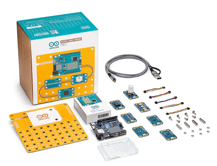
Arduino Plug and Make Kit
The Arduino Plug and Make Kit features the ...
| SKU: | |
|---|---|
| Stock: | 968 |
| Cost: | $66.97 |
300361-0011
Molex
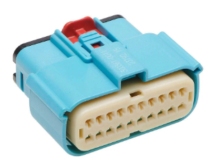
MX150 Mid-Voltage MatSealed Female Connector Assembly, Dual Row, 20 Circ...
| SKU: | |
|---|---|
| Stock: | 280 |
| Cost: | $2.51 |