Using capacitive sensors for proximity detection
Capacitive sensors can form a cheaper way to build a proximity antenna than using infra-red technology and consume less power.
Traditional extended range proximity sensors have used infra-red technology, which suffers from both high costs and high power consumption. Capacitive sensing, on the other hand, can provide a lower cost and lower power alternative.
A typical application would be a proximity antenna, also known as a capacitive pad. Design elements include the size of the antenna, location of the antenna in relation to a ground plane and specific settings within the capacitive sensor, in this case a RightTouch device from Microchip Technology subsidiary SMSC. Adhering to a few simple guidelines allows the unique design of the RightTouch device to detect the approach of a user or the movement of nearby metallic objects.
There are three critical physical design elements needed to achieve maximum range detection with high signal strength and low noise. First, the distance between the antenna and a ground plane needs to be as large as possible; the ground plane in this case could be any layer of the PCB or nearby metallic objects. Secondly, the antenna needs to be as big as possible. And, thirdly, antenna movement within the system must be restricted using double-sided tape, adhesives, clips and so on.
The initial design begins by defining both the range and the function. For example, a 5cm range for approach detection in a monitor button board, or 25cm for approach detection in a 25cm digital photo frame.
Ground plane
Any ground plane or metal surface near the antenna will decrease the range of proximity detection. Ground planes have two effects on proximity. The first is they shield the approaching object if placed in the path of the object, effectively reducing the range of the sensor. The second is they increase base capacitance when placed directly below or adjacent to the proximity antenna.
In free space, an antenna can emit and sense freely in all directions with little attenuation. When a ground plane is introduced, signals emitting or being sensed from or by the antenna want to terminate on the ground plane. As the distance between the ground and antenna decreases, the strength of the field radiating decreases. So as a ground plane is placed closer and closer to the antenna, the sensing range is effectively reduced.
A ground plane also increases the capacitance of the antenna compared with an identical antenna in free space. Large antennas close to a ground plane (such as a 25cm2 solid pad with a solid ground plane on a 0.08cm two-layer PCB) will exceed the calibration range of SMSC devices.
Antenna shape and construction
Every system design is unique with specific aesthetic goals as well as physical constraints. Loop antenna shapes – large trace with empty centre – suit large applications such as photo frames and keyboards. Solid pads are better for smaller button board applications. Loops reduce the overall capacitance the device will see and create a larger coverage area. A pad shape suits small boards where separation from ground is limited and the pad area is needed to create the desired range.
A loop antenna can have any aspect ratio, for example 20x20 or 5x40cm. The desired function and form factor will guide this decision. Loops as small as 1x1cm create a small degree of proximity. Loops of 30x30cm (30AWG wire) will create a large proximity envelope. Larger loops or thicker gauge wire may exceed the calibration range of the device, so it is recommended that the total base capacitance is kept to 45pF or less to prevent out of range conditions, over temperature or other unique situations such as calibration with debris on the sensor.
If a pad is best for the application, any shape can be used. A long and thin pad of 1x25cm (25cm2) would be well suited for the bottom or side of an LCD monitor. If space is available, a large 5x5cm (25cm2) pad will create a large dome of proximity detection. A circular pad with a radius of 2.83cm (about 25cm2) would provide a similar dome of proximity.
If the capacitance is too large, the shape could be converted to a loop by removing the centre area of the square or circle.
Physical shapes are unlimited. Antenna shapes can include circles, ovals, squares, rectangles or even serpentine around boards. The overall effectiveness of the antenna is not determined by the shape but rather the area of the conductor relative to the user or object entering the proximity zone. Proximity range is directly proportional to antenna size. Larger antennas provide greater proximity detection ranges.
Loop antennas can be created with solid copper wire with or without insulation, flex circuits or on a PCB. In the case of a wire, solid core or stranded will perform similarly, however solid core is easier to assemble in the manufacturing process. Larger gauge wire will provide increased range due to the increased surface area. The physical design will limit the size of the wire that can be used.
Designs can start with 30AWG and increase until the desired range is achieved, aesthetic design limits are reached or calibration limits are reached.
In the case of a PCB loop antenna, the larger the trace width, the larger the range. A minimum trace width of 0.18mm will function as an antenna, but larger traces will produce greater range.
Solid PCB pad shapes need to follow the same guidelines, that is increase area and keep nearby ground to a minimum.
Configuration
Once the antenna has been designed and assembled, software must be written to configure it properly for proximity. There are two critical software programming elements to achieve maximum range detection with high signal strength and low noise. First is increase gain and sensitivity in the device and the second is to reduce the average noise.
In the SMSC range, there are two types of device for proximity. One uses built-in proximity modes (CAP1114 and CAP1214), while the second relies on user-defined modes (CAP1188 family).
One proximity example is a digital photo frame with a very large loop antenna constructed of sold wire. Second is a button board with a long and thin antenna to detect a user and illuminate the functions of the buttons. And thirdly is the SMSC EVB-CAP1188 that can demonstrate both a long and thin pad as well as a PCB based loop antenna.
For the first, the goal is when then the user approaches the frame from any direction, at about 25cm the LEDs turn on to indicate the position of the touch sensors, as shown in Figure 1.

Figure 1 - On the left, the LEDs are off but as a hand approaches the LEDs turn on, as seen on the right
Here, the exterior enclosure measured 25x20cm, the LCD 17.5x19cm and the antenna 24x19cm. The proximity wire used was 24AWG and the calibrated capacitance 45pF. The proximity range was between 24 and 26cm.
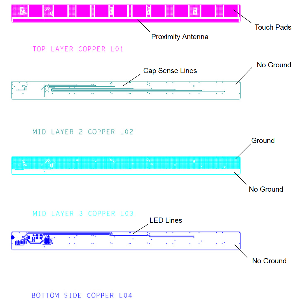
In the second example, shown in Figure 2, the goal is to detect the user approaching the button board from the front or side with the LEDs turning on at just above 5cm distance to show the icons that indicate the functions of the sensors.

Figure 2 - Gerber view of the button board
Here, the board measures 190x15mm and the proximity antenna 188x2.5mm. There is no ground under the proximity antenna on any layer. The calibrated capacitance is 15pF and the proximity range 7cm.
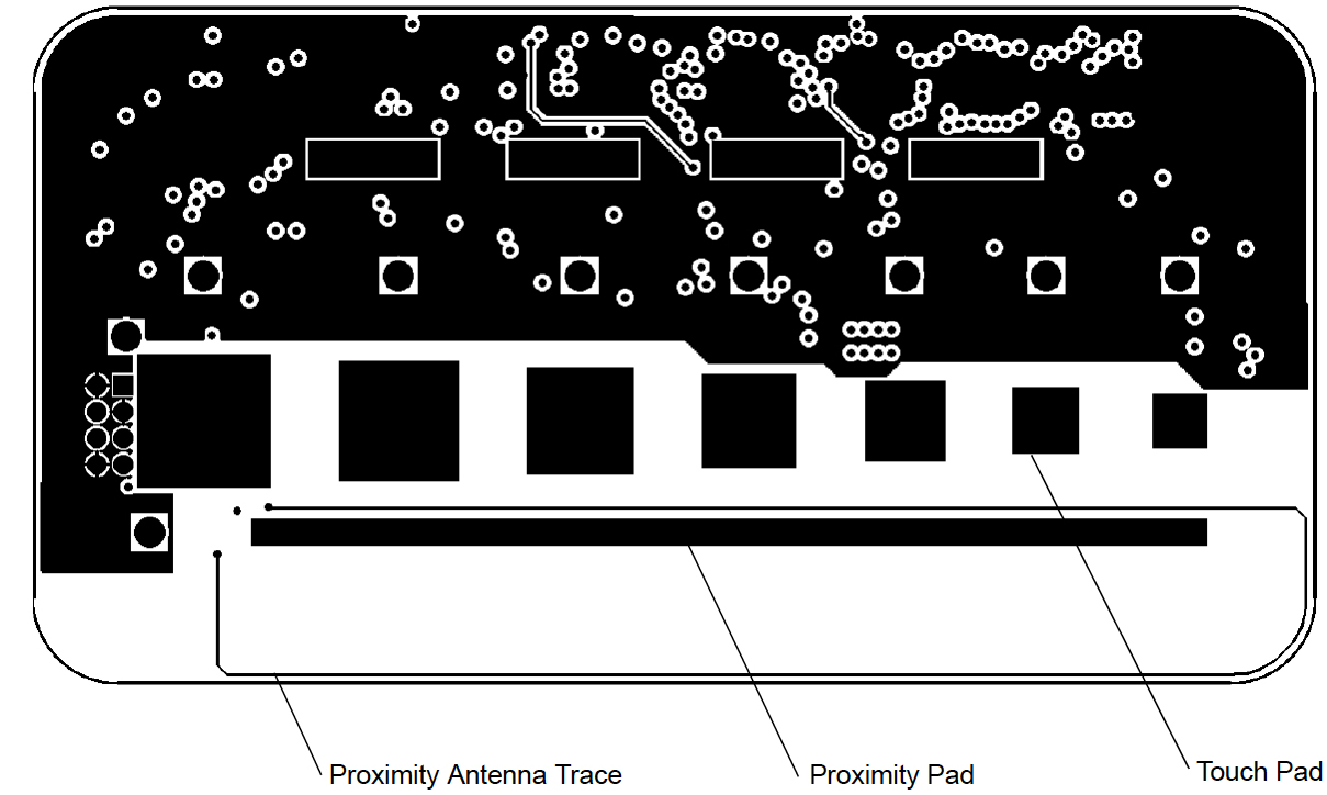
In the final example of a small loop antenna, see Figure 3, the user approaches the board from the front and at just above 6cm the LEDs turn on to indicate the proximity range.

Figure 3 - Gerber view of EVB-CAP1188
In this case, the board measures 95x50mm with the proximity loop measuring 82x10mm; the touch pad is not connected. The proximity wire dimension is 0.18mm trace and there is no ground under the proximity antenna on any layer. The calibrated capacitance was 44pF but reduced to 37pF due to the long trace from the chip to the antenna and many vias. Proximity range was 6cm.
Other considerations
Following the basic design rules outlined here will provide a robust proximity design. Occasionally, a system will have rigorous design requirements beyond the typical. For example, in a high RF noise environment it may be necessary to add a 5 to 15pF capacitor to ground near the device to provide an RF path before entering the device. Adding a small amount of ground under the proximity pad can also provide an RF path. And a 100Ω (maximum 500Ω) series resistor can create a small RC filter to shunt noise before entering the device.
If the base capacitance is greater than 50pF, then adding a 25 to 40pF capacitor in series with the proximity pad can bring it back into range. It is also worth trying reducing the proximity pad area and reducing the ground area under and around the proximity pad.
Conclusion
The designs here show three different ways the RightTouch capacitive sensor family can be used in proximity sensing systems with ranges from 4 to 26cm rather than more expensive power hungry infra-red technology. The devices are also suitable for sensing down to 1cm and up to 28cm.


