Understanding the encoder resolution
An incremental rotary encoder can be used to measure rotational direction, speed and angular displacement. The encoder generates two output channels as it rotates, A and B. Each output is a square wave, and in a quadrature encoder, the two outputs are 90° out of phase.
By Jason Kelly, Motion Control Design and Applications Engineer, CUI Devices
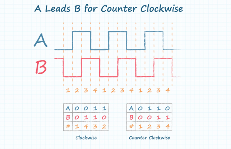
The relationship between the two phases enables the direction of rotation to be determined, as figure 1 shows. Some encoders also generate an index pulse at one or more positions in each revolution, which can be used to indicate a specific location.

Figure 1. The phase relationship between channels A and B indicates the direction of rotation.
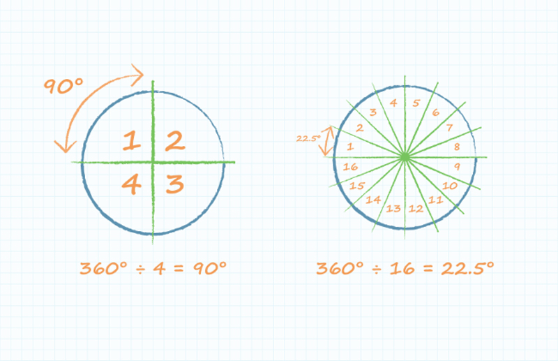
To calculate the rotational speed and angular displacement, the encoder’s resolution must be known. The resolution expresses the number of mechanical degrees the encoder turns between each pulse of the square wave (figure 2). When this is known, the pulse rate indicates the rotational speed, while the pulse count between a start and end point indicates the number of degrees turned.

Figure 2. An encoder of higher resolution can measure smaller increments of angular displacement.
Encoder resolution can be expressed in several ways, such as Pulses Per Revolution (PPR), Counts Per Revolution (CPR) or Lines Per Revolution (LPR). Other commonly used terms include Periods Per Revolution and Cycles Per Revolution. Each expresses the encoder’s granularity, although there are subtle differences that can leave room for confusion, so users need to understand the appropriate meaning to interpret the encoder outputs correctly.
CUI Devices always uses the term PPR to describe Pulses Per Revolution for its range of modular and panel-mount incremental encoders. These are available with resolutions ranging from 10 PPR to 4096 PPR, which describes the number of high pulses the encoder will generate on either of its square-wave outputs.
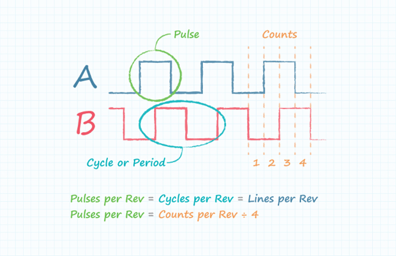
In practice, encoder resolution expressed as periods, cycles or lines per revolution would give the same number. However, if a manufacturer expresses the resolution in terms of CPR, it is important to find out whether the meaning is Cycles Per Revolution or Counts Per Revolution because the difference is significant.
The channels A and B create a 2-bit output that has four possible states, as shown previously in figure 1. Hence there are four counts in each complete cycle, so that CPR - meaning Counts Per Revolution - is four times the PPR, whereas Cycles Per Revolution is equivalent to PPR. Figure 3 compares the terms.

Figure 3. There are four times as many Counts Per Revolution as pulses, cycles or lines.
Therefore, if the manufacturer’s datasheet states the resolution in terms of CPR, the user needs to understand whether this refers to Counts Per Revolution or Cycles Per Revolution. The two terms differ by a factor of four, which would certainly cause errors in speed and displacement measurements.
Getting the datasheet figures into the same format is important when comparing encoders from different manufacturers. This can be done by inspecting the waveforms or timing diagrams for each product. Calculating the pulse interval in degrees or arcminutes provides a reliable reference for comparison.
Our Encoder Product Spotlight provides more guidance about understanding and using incremental encoders.


