EV contactors capable of interrupting high voltage currents
The European distributor for LSIS, Willow Technologies, presents a detailed look at LSIS’ new range of GER series Electric Vehicle (EV) contactors, what they are, why we need them and how they are able to cope with EV motor controller demands in small to medium size vehicles of all types, easily fitting in to confined spaces, capable of interrupting high voltage DC currents repeatedly and interrupting high short circuit currents in an emergency.
Electric Vehicle (EV) contactors primarily act as the main contactors in electric vehicle drive circuits in all sizeable electric vehicles: cars, trucks, boats and rail locomotives. The main contactor’s function is to open under a potential short circuit load (up to 3,000A or more) making the motor drive electronics as safe as possible, both in the general running of the vehicle and in a crash situation, where a potentially damaging, high current short circuit, might occur, resulting in a fire. They only need do this once! But they must work…
The key features
To summarise the key features of the GER range, they have a high short circuit current rating up to 3,200A at 450DC, a high short term overload current up to 900A and a continuous current capacity of up to 400A at 450VDC. The compact GERs each feature magnetic ‘arc blow out’ and a special inert gas fill.
The process
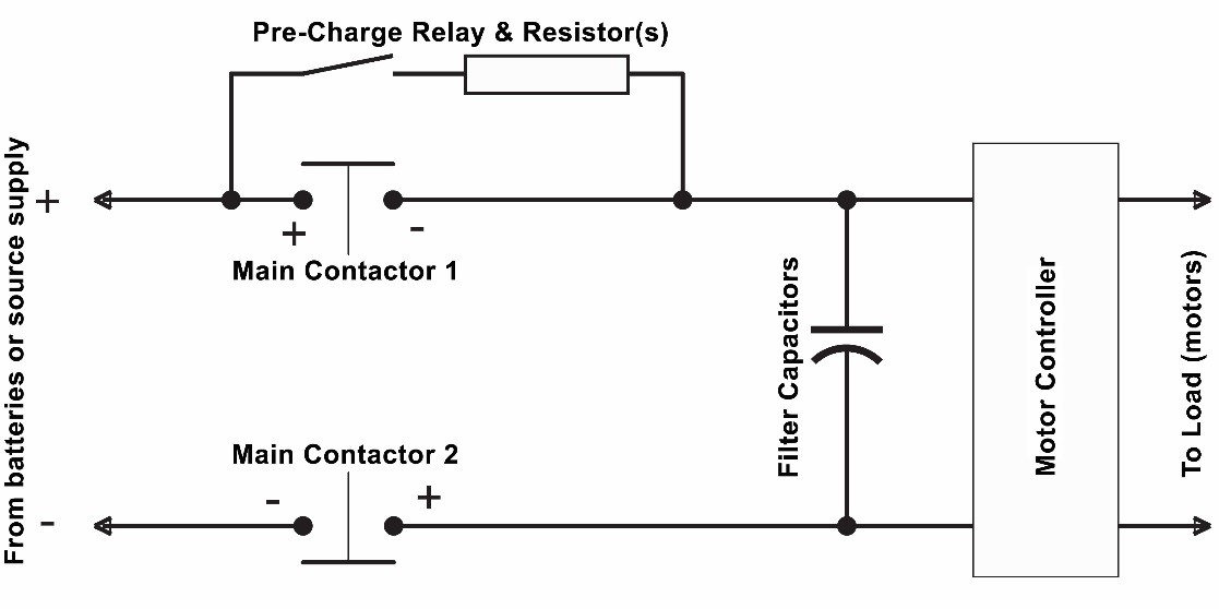
Typically, an EV motor control system will have a large bank of filter capacitors which can generate a huge inrush. In a vehicle, there will be a pre-charge relay or contactor such as the LSIS GER010, GER020 or GER040. This pre-charge relay is wired in series with a current limiting resistor. The pre-charge relay closes first and the current flows into the filter capacitors which, when discharged (empty), will need to charge up to about 80 or 90% in order for the system to activate the two main LSIS GER contactors, which close to carry the motor ‘run’ current (LSIS’ GER100, GER150, GER250 and GER400 are all designed to be used as main contactors).

Example Electric Vehicle engine circuit schematic (At least five HVDC contactors would normally be used).
When the main contactors close, the pre-charge contactor (having performed its function) opens to disconnect the resistor and avoid excess heat and power wastage. At the point the main contactors close, the vehicle is stationary and the filter capacitors are now charged sufficiently for the vehicle to move. The motor drive electronics take over and the full motor current flows through the main contactors as required by the drive electronics. This whole process occurs extremely quickly so the driver doesn’t notice, it’s like turning on the ignition of an internal combustion engine car. When the driver pushes the vehicle stop button (turns off the ignition), the main contactors open, isolating the batteries from the motor and drive electronics.
Repeated short term lower level current overloads
LSIS GER series contactors are constructed to guard against damage to the contactor itself and therefore to the vehicle electronics and source of energy (i.e., the battery). In normal use, the main contactors will experience repeated short term lower level current overloads, for example; as the vehicle accelerates. However, in the event of a major incident (e.g. vehicle crashes), the GER main contactors must open to avoid potentially damaging extremely high short circuit currents with the potential for fire and injury.
Switching high voltage DC at high currents requires special techniques to cope with the resultant arcs that occur within the GER contactors. The filter capacitors in the vehicle circuit act as a sponge to draw electrical charge as fast as possible. When they are empty, the inrush spike would be damaging but the resistor limits the charge current to around 10A. As the contacts of the contactor open, a resultant arc begins to form between its two contacts. The temperature of the arc reaches millions of degrees centigrade (akin to a lightning bolt!) and generates a transfer of material from one contact to the other, resulting in a pip and a pit in the newly melted contacts and causing the contactor and consequently the vehicle to fail.
How LSIS GER contactors overcome the potentially damaging electrical arc
Firstly, the contacts are enclosed in a hermetically sealed chamber filled with a special inert gas and are strategically designed with wide air gaps and a bridging contact. The inert gas greatly inhibits arc formation and extends normal switching life.
Secondly, the GER Contactors have a double break contact configuration. One or more magnets fitted inside the chamber are positioned such, that as the main contacts open and an arc begins to form, the magnets simply stretch that arc away from the contacts (blow it out). The arc paths become stretched to an unsustainable level thus the arc is extinguished – or blown out.
Applications
The GER100, GER150, GER250 and GER400 can all be used as main contactors and the GER010, GER020 and GER040 can be used for the pre-charge relays. While mainly used in electric vehicles, particularly in the Battery Disconnect Units (BDUs), these contactors can be used in any applications where the need to switch high voltage DC exists, such as solar panels or test equipment.


