Using SiC devices in a three-phase motor drive application
SiC (Silicon Carbide) MOSFET modules with blocking voltages of 1,200V and RDSON values as low as 20mΩ, offer a real alternative to 1,200V Si IGBTs in motor drives. John Mookken and Julius Rice, Cree, explore the economics of using the more expensive SiC module with the performance gains and added complexities at the system level.
Silicon IGBTs have long been the switch of choice in motor drives. Traditionally, silicon MOSFETs with blocking voltages of 1,000V or more have been costly, performed poorly and with limited availability. IGBTs have become standard in 480V two level inverters in motor drives. IGBTs’ high switching losses limit their practical switching frequencies (Fsw) to less than 10kHz.
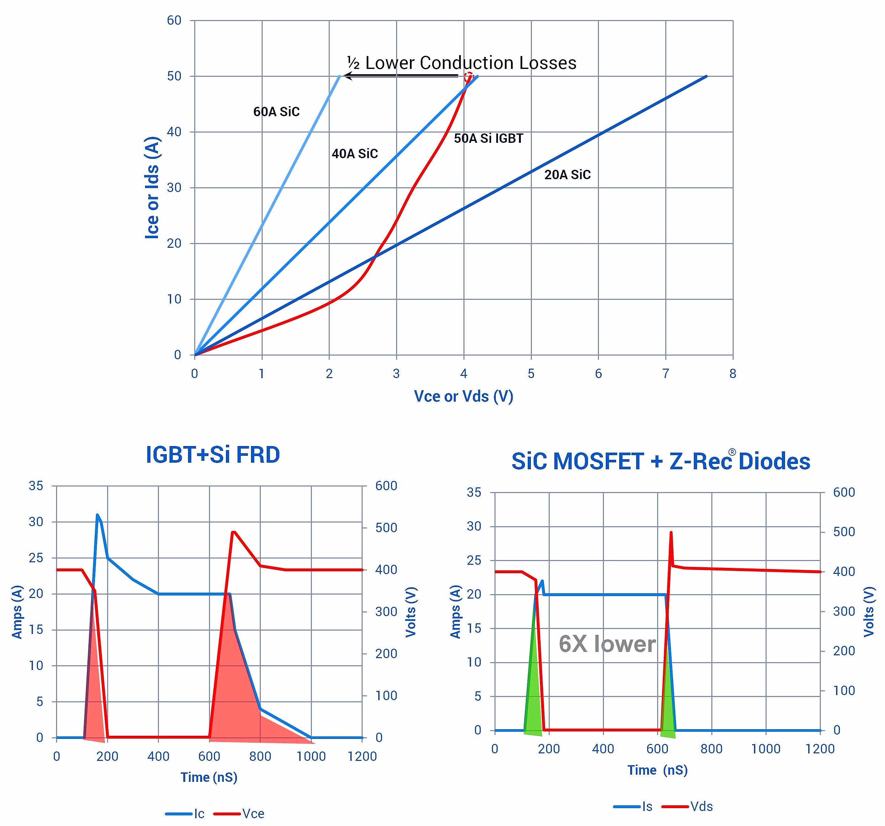
A silicon IGBT takes a long time to turn off due to its characteristic tail current, which increases turn-off losses in the IGBT. SiC MOSFETs have no minority carriers and thus no tail current, so, their turn-off losses will be significantly less (typically six times lower than an IGBT). Not only do SiC MOSFETs have significantly lower switching losses, but they also have lower conduction losses. (See Figure 1a, which shows the forward I-V curve for a SiC MOSFET compared to an IGBT). The total SiC MOSFET switching losses (Eon+Eoff) decreases slightly with increase in device junction temperature, while the opposite is true in Si IGBTs. The combination of lower switching and conduction losses in SiC devices dramatically reduces system losses and increases overall efficiency of systems in which they are used.

Figure 1: Comparison of conduction and switching losses in Si IGBTs and SiC MOSFETs
Another key advantage in the selected SiC module is the inclusion of SiC junction barrier Schottky (JBS) diodes as free-wheeling diodes in the circuit versus fast recovery Si diodes used in Si IGBT modules. SiC JBS diodes have no minority carriers, so they have virtually no reverse recovery losses like silicon PiN or fast recovery diodes, providing an additional efficiency improvement in the SiC module motor drive inverter. (Figure 1b shows the total switching loss effect of these SiC JBS diodes and MOSFETs when compared to a similarly rated high speed IGBT+fast recovery diode.
Motor drive test set-up
To measure the SiC MOSFET module performance advantages over competing IGBTs, a three-phase motor drive test set-up was built to enable either an IGBT module or a SiC MOSFET module to be used as the power devices in a three-phase inverter. A TI Stellaris DSP controller generated control signals with modulation by an open loop space vector. A differential voltage probe placed across two of the phases measured the dv/dt at the inverter output terminals.
The SiC module used for the comparison in this case is a new generation of Cree SiC MOSFETs (CCS050M12CM2) in an IGBT package. The module contains six Gen2 50A/1200V MOSFETs and six 50A/1200V JBS diodes connected in anti-parallel with each MOSFET. The Si IGBT module chosen for the comparative is Infineon’s FS50R12KT4_B15. It was selected because it comes in the same physical package as the SiC MOSFET module and has similar electrical ratings.

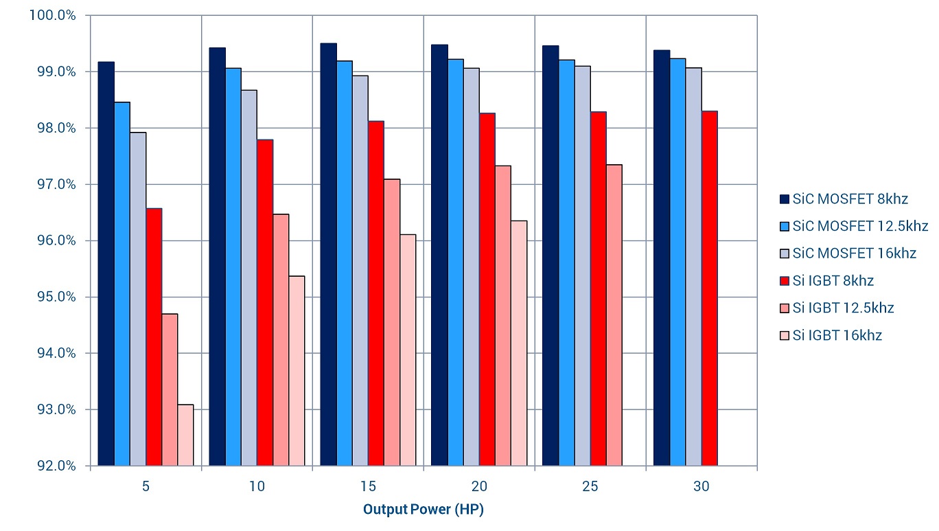
Figure 2: Measured efficiency of inverter at various power levels and switching frequencies (Fsw)
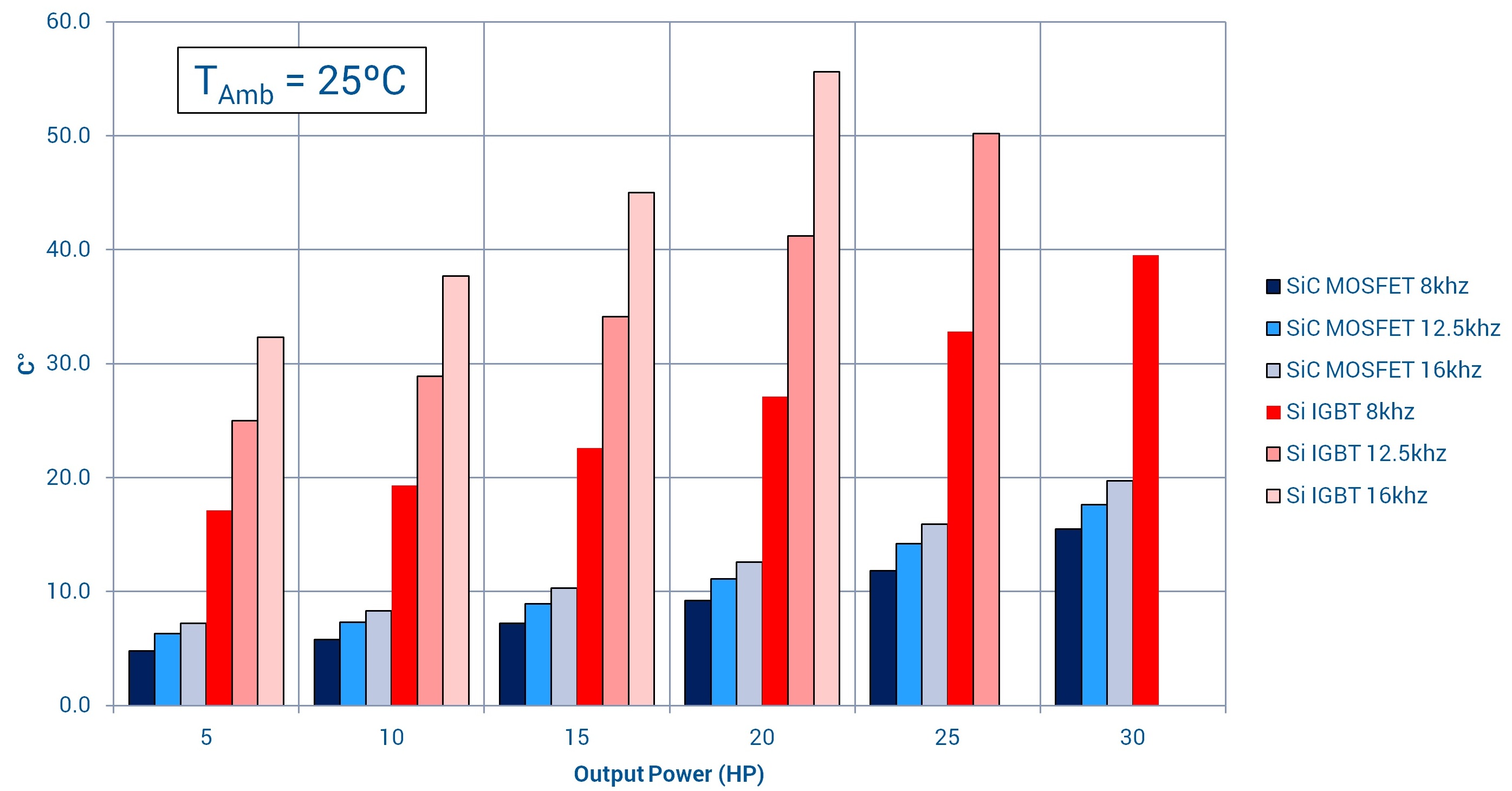
Motor drive efficiency measurements were made using a Yokogawa WT1600 digital power meter. The inverter heatsink temperature was measured with an embedded thermocouple directly underneath the module baseplate. This allowed the heatsink’s temperature rise above ambient to be monitored (see Figure 3).
The motor used was an Allen-Bradley® 50hp/3-phase induction motor with a load provided by a Magtrol Eddy Current Dynamometer (Model 2WB15) controlled with a Magtrol DSP6001 dynamometer controller. Applied voltage to the motor was 460VAC (60Hz), with loads from 5 to 30hp in increments of 5hp. Motor drive efficiency was measured at 8khz, 12.5kHz, and 16kHz switching frequencies to see the effect on performance at higher Fsw.
Due to increased losses and limitations of the test setup, the Si IGBT could only be operated up to 25hp at 12.5kHz and 20hp at 16kHz.
Dv/dt measurements
Maximum dv/dt was measured on both Si IGBT and SiC MOSFET test configurations. Several different values of external gate resistance (RG) were used to show the correlation between measured maximum dv/dt and RG. Figure 4 shows how maximum dv/dt is influenced by RG.
Excessive dv/dt places voltage stress on the motor’s winding insulation. The goal is to limit dv/dt to a value comfortably lower than inverter duty rated motors or conform to NEMA MG1-2006 (approximately 16kV/µs).
The easiest method to reduce peak dv/dt is to slow the device switching speed by increasing RG. However, this increases switching losses. A “worst case” scenario involved RG at 40Ω, which keeps peak dv/dt values below 10kV/µs while only losing approximately 0.2% in overall efficiency.
Another means of mitigating excessive dv/dt is through the use of a sine wave or dv/dt filter. A sine wave filter connected between the inverter and the motor terminals can add cost and efficiency penalties to the system if the drive did not already include an output filter.
SiC economics
Although the SiC module is $200 more expensive, (around four times that of a Si IGBT module), reduced losses and resulting overall efficiency gain show significant savings when product life cycle costs are included.

Figure 3: Measured heatsink surface temperature rise above ambient
Restricting switching frequency to 8kHz and maintaining output dv/dt at 10kV/µs by using a high RG value of 40Ω is considered unfavourable for SiC devices because at higher switching frequencies the economics are more favourable for SiC.
The efficiency measurements prove that SiC MOSFET modules offer reduced losses versus Si IGBTs even at relatively low switching frequencies (8kHz). As carrier frequency increases, performance improvement between SiC MOSFET modules and Si IGBT modules increased. In new motor drive designs, reduction in losses creates system cost savings by relaxing cooling requirements; by reducing system size using higher switching frequency; or by increasing power density in an existing package.
System efficiency gains alone can justify specifying SiC MOSFETs over traditional Si-IGBTs in many motor drive applications if life cycle costs of the motor drive product are considered. This is true even when some of the efficiency gain of SiC is traded with higher RG values to keep the peak dv/dt values in check.


