Use a PGIA to avoid getting burned by switch parasitics
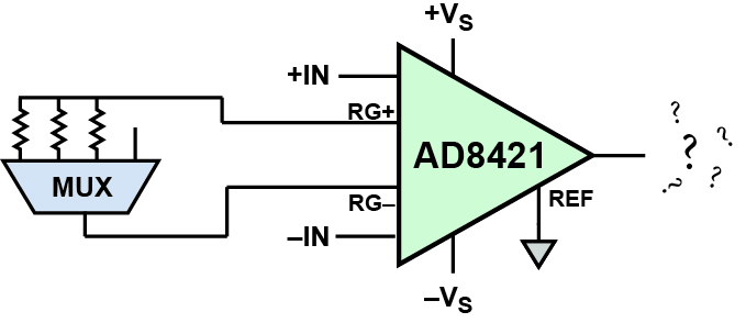
Instrumentation Amplifiers (In-Amps) with programmable gain are typically used to maximise dynamic range in precision sensor measurements. Most in-amps use an external gain resistor, Rg, to set the gain, so the desired gains can be achieved by multiplexing a set of resistors. Three major issues must be considered before implementing a system this way, however: supply limitations, switch capacitance and on-resistance.
By Scott Hunt, Product Applications Engineer, Analog Devices.
Solid-state CMOS switches require a power supply. When the source or drain voltage exceeds the supply, fault current will flow, possibly causing an incorrect output or latch-up. The voltage at each Rg pin is typically within a diode drop of the voltage at the corresponding input, so the signal voltage range of the switch must be greater than the input range of the in-amp.

The switch capacitance acts like a capacitor hanging on one of the Rg pins, while leaving the other Rg pin alone. A large capacitance could cause peaking or instability, but the effect on the common-mode rejection is more important. In the PC board layout, the ground plane is generally removed beneath the Rg pins because a capacitive imbalance less than 1pF greatly reduces the AC CMRR. The switch capacitance can be in the tens of picofarads, causing large errors. A low-capacitance switch or a balanced switching architecture can be used, with each gain resistor divided in half and two multiplexers connected in the centre to select them.
Finally, the on-resistance of the switch impacts the gain. More importantly, the on-resistance of the switch changes with the drain voltage, specified as Rflat_on. The change in switch resistance vs. the gain resistance creates a gain nonlinearity. For example, an Rg of 1kΩ and a switch with 10Ω Rflat_on, will cause a 1% gain uncertainty over the common-mode range. A certain portion of that will translate to the differential signal (a 2Ω change would cause 2000ppm nonlinearity). The balanced switching architecture is the best method when the inputs are driven differentially because the switch drain voltage is set by the input common-mode voltage, but the gain uncertainty is still an issue. A low on-resistance switch can be used, but these typically have higher capacitance.
If possible, use reed relays rather than solid-state switches to reduce the parasitics.
A much less complex, high performance solution is to use an integrated Programmable-Gain Instrumentation Amplifier (PGIA) such as the AD8231 or the AD8250. Or, an in-amp such as the AD8237 can implement arbitrary programmable gains.
 |
Author Profile: Scott Hunt is a product applications engineer in the Linear Products Group in Wilmington, MA. Scott joined Analog Devices in 2011 after receiving a bachelor’s degree in electrical engineering from Rensselaer Polytechnic Institute. Scott specialises in integrated precision amplifiers including instrumentation amplifiers, differential amplifiers and thermocouple amplifiers. |


