
Ultra-low power button reset solution
By Rostyslav Marushchak, Applications Engineer, Renesas Electronics, Lviv, Ukraine
This article originally appeared in the April'24 magazine issue of Electronic Specifier Design – see ES's Magazine Archives for more featured publications.
The ultra-low power button reset solution is a significant application in widely distributed digital devices such as smartwatches, smartphones, wireless headphones, tablet PCs, and other small devices that have high requirements for low power consumption and battery life.
This article explains how to develop a design with an on/off button with GreenPAK, which an active current consumption is close to 500nA.
The operation of the design is founded on the low-frequency watchdog pulse generator, the button push detector, and a set of logic for generating a reset pulse with or without delay.
Also, the GreenPAK still has enough macrocells and configurable PINs to adapt the design to the specific needs of the customer.
Operation of the ultra-low power button reset with GreenPAK
Weselected three GreenPAK devicesto check and evaluate the level of current consumption: SLG46140, SLG46811, and SLG46855.The internal design was implemented in the Go Configure Software Hub.
Since the main task of the device under development is a constant check of the condition of the external button (on/off) with minimal current consumption, for clock delay blocks and counter blocks in the design a low-frequency oscillator is used.

Figure 1. Application circuit with SLG46140

From the low-frequency watchdog pulse generator (WD) the low-frequency pulses, through the 1M resistor, are applied to the ‘Button’ input PIN. Also, the S1 button is connected to the ‘Button’ PIN, which when pressed pulls down it to the GND. This allows to determine the condition of the button (on/off) using a frequency detector and generate a reset pulse to the RESET output PIN with delay time or without it (see Waveform 1. The main design functionality and Figures 1-6).
Channel 1 (yellow/top line) –Button
Channel 2 (light blue/2nd line) –RES_DLY ON/OFF
Channel 3 (magenta/3rd line) –RESET
Figures 1,3,5 and Figures 2,4,6 show the circuits of the proposed application and the design block diagrams for each selected device.
Table 1 shows the current consumption values for the SLG46140 at different values of the period of the frequency of the low-frequency watchdog generator to determine its optimal settings.

Figure 2. Block diagram of the design for SLG46140
As can be seen from the data given in Table 1, the lowest current consumption is at Tw/s = 200ms, so the rest of the data will be taken at Tw/s = 200ms. See the data in Table 2-4.


Conclusion
The current consumption values shown in Tables 1-4 are the average values of more than 200 measurements for each value, measured with a Digital Multimeter SIGLENT SDM3065X.
As we can see from the data given in Tables 2-4, the current consumption for SLG46140, SLG46811, and SLG46855 is close to 500nA but the lowest current consumption measured for SLG46855 is less than 500nA, so it can be considered that the goal has been achieved.
In addition, there are still many unused resources that can be furthermore used depending on the needs of a customer.


Product Spotlight
TBF10SL-4PS-B
ITT Interconnect Solutions
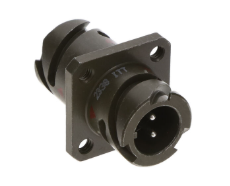
| SKU: | 1003-TBF10SL-4PS-B-ND |
|---|---|
| Stock: | 50 |
| Cost: | $45.59 |
CAA572C0G3A663J640LJ
TDK Corporation
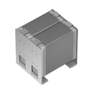
| SKU: | |
|---|---|
| Stock: | 1037 |
| Cost: | $9.16 |
RA1113112R
E-Switch, Inc.
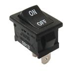
| SKU: | EG5619-ND |
|---|---|
| Stock: | 5586 |
| Cost: | $0.55 |
R30-3002002
Harwin

| SKU: | 952-1510-ND |
|---|---|
| Stock: | 6545 |
| Cost: | $0.76 |
NRF54L15-QFAA-R
Nordic Semiconductor
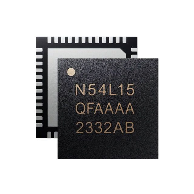
| SKU: | 4823-NRF54L15-QFAA-RTR-ND |
|---|---|
| Stock: | 0 |
| Cost: | $2.39 |
STDRIVEG611Q
STMicroelectronics
| SKU: | 497-STDRIVEG611QTR-ND |
|---|---|
| Stock: | 0 |
| Cost: | $2.63 |
TBF10SL-4PS-B
ITT Interconnect Solutions
| SKU: | 1003-TBF10SL-4PS-B-ND |
|---|---|
| Stock: | 50 |
| Cost: | $45.59 |
CAA572C0G3A663J640LJ
TDK Corporation
| SKU: | |
|---|---|
| Stock: | 1037 |
| Cost: | $9.16 |
RA1113112R
E-Switch, Inc.
| SKU: | EG5619-ND |
|---|---|
| Stock: | 5586 |
| Cost: | $0.55 |
R30-3002002
Harwin
| SKU: | 952-1510-ND |
|---|---|
| Stock: | 6545 |
| Cost: | $0.76 |
NRF54L15-QFAA-R
Nordic Semiconductor
| SKU: | 4823-NRF54L15-QFAA-RTR-ND |
|---|---|
| Stock: | 0 |
| Cost: | $2.39 |
STDRIVEG611Q
STMicroelectronics
| SKU: | 497-STDRIVEG611QTR-ND |
|---|---|
| Stock: | 0 |
| Cost: | $2.63 |