Optimising automotive pre-boost power supplies
In the first part of a three part feature, Matthias Ulmann of Texas Instruments describes the problem involved in designing and optimising an automotive pre-boost power supply, shows the impact of a cold start test pulse on such a supply, and discusses a typical pre-booster specification.
With each new generation, modern cars provide more and more electronic assistance and comfort. Some of them, like Advanced Driver Assistance Systems (ADAS), improve safety through the use of radar sensors and cameras. Other sub-systems, such as infotainment applications, make driving a more relaxed experience. Common to all these systems is the power source - the car’s battery.
As more and more cars feature an automatic start-stop for fuel saving, a stable battery voltage is not guaranteed at all times. Whenever the starter motor is activated and the engine is started, the battery voltage drops due to the high current and internal resistance of the battery. Depending on the battery’s quality and temperature, the voltage drop can be so significant that the electronic systems shut down. From a safety perspective, this is not a problem for comfort or infotainment systems. However, if the traffic light turns to green and the throttle pedal is pressed, it is not acceptable that important safety systems switch off and need to start up again. And even for the infotainment or navigation systems, it is inconvenient if you have to re-listen to the first track of a CD or re-enter the destination after every stop.
To avoid such an outage, different options are possible. Critical electronic systems can be either supplied by a buck-boost converter, which is continuously switching, or by a so-called pre-booster. This is a boost converter in front of the actual system, which provides a voltage high enough to ensure that the system doesn’t shut down, even when the battery voltage fluctuates. At first glance, designing such a pre-booster sounds easy, but it can be more difficult if both good performance and low cost are required. Several pre-conditions have to be considered and the performance depends on different components.
The cold start test probe
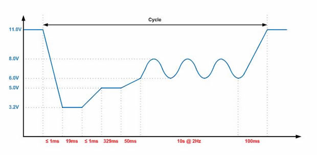
As already mentioned, the battery voltage drops more or less when the starter motor is activated. This depends on several factors and cannot be predicted. Different standards were therefore released, reflecting a couple of scenarios. One of the worst types of cold start pulses from the perspective of an electronic system is the cold start test pulse ‘severe’, as defined in the LV 124 standard (Figure 1).

Figure 1 - cold start test pulse "severe"
The most critical point is at the beginning of the pulse, when the input voltage drops from 11V down to 3.2V. This is almost like unplugging the device from the battery. Then the voltage remains at 3.2V for 19ms until it recovers up to 5V, where it stops for a comparatively long time of 329ms. Afterwards the voltage increases further and forms a sinusoidal waveform between 6V and 8V with a frequency of 2Hz for ten seconds. Finally, the voltage settles back at the initial value of 11V. To test a system, this pulse is applied ten times in a row with a break of two seconds between cycles.
This pulse represents the battery voltage when the starter motor is used to start the engine. A starter motor is a series DC motor with the field winding and armature winding in series. It provides heavy starting torque but therefore needs a large initial current as well. This large initial current and the internal resistance of the starter battery causes a drop of battery voltage, down to 3.2V for this specific test pulse.
After the current and therefore the flux are high enough, the motor starts to turn and cranks the engine. This point is represented by the beginning of the sinusoidal waveform. While the compression of the cylinders is low, the battery voltage recovers up to 8.0V and while the compression is high, the battery voltage falls down to 6V. The motor needs some time until the engine is running, represented by the ten seconds of the sinusoidal waveform. After this time the engine is running and the battery voltage settles back at its initial voltage of around 12V.
The biggest challenge for a pre-booster is to handle the breakdown of the battery voltage from 11V down to 3.2V within 1ms or less. If the booster is able to handle this part of the operation, the rest of the pulse is not a problem. Thus other test pulses are then typically easy to handle.
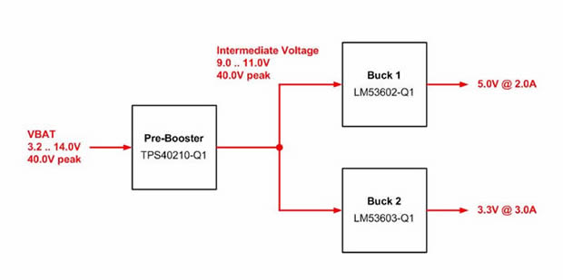
An automotive power tree (Figure 2) usually provides several voltage rails such as 5V and 3.3V which are generated by buck converters. These voltages are higher than the worst case minimum input voltage of the battery, which is 3.2V. As those systems incorporate reverse polarity protection as well, the input voltage for the buck converters is even lower than 3.2V.

Figure 2 - automotive power tree
The pre-booster has the task of providing a voltage for the buck converters which is always higher than their output voltages, plus additional headroom. For this design, the output voltage of the pre-booster is set to 9V. Thus the input voltage of the bucks will always be between 11V and 9V and enables them to provide a stable output voltage without any impact from the battery’s breakdown. Of course, the input voltage range of the bucks has to be even higher. Standards define peaks of up to 40V and continuous operation with 27V input voltage for one minute.
The boost converter is supplied and enabled all the time. It will not switch as long as the input voltage is higher than the output voltage, incorporating all losses such as the forward voltage drop of the two diodes (reverse polarity protection and booster diode) and the DC resistance of the inductor. For simplification these losses are not considered and it is supposed that the booster is not switching as long as the input voltage is above 9V and switching if it’s below 9V.
Now, as soon as the battery voltage is lower than 9V, the converter starts automatically switching to maintain a stable output voltage of 9V. However, there are two problems. First, the converter needs to start switching but it is not possible to provide the full power to the output without a delay. How fast it starts depends on the bandwidth of the converter’s frequency response, and will be explained later on. Second, the input voltage breaks down not only to a very low level but also very quickly. That means that while the booster is starting to switch, the input voltage drops at the same time, which obviously makes things worse.
The bottom line is that the booster’s output voltage will always show a dip below the nominal output voltage at this point. Depending on the design of the pre-booster and the load, this dip can be small or large. A relatively large headroom of 4V between the booster and the highest buck output voltage allows a voltage dip up to 2-3V. However, this also depends on the maximum duty cycle of the subsequent converters and their line regulation capabilities. The smaller the headroom, the more difficult and pricey the design of a pre-booster.
Specification
A typical short specification for a pre-booster could look like this:
If nothing else is specified, it is likely that the booster has to work with the lowest input voltage of 3.2V just for a very short time as specified in the test pulse. This implies that the booster has to be designed to cover such a low input voltage from an electrical standpoint, but not from a thermal one. However, some tests also incorporate a very slow ramping-down of the battery voltage resulting in a continuous operation, even at low input voltages like 6V.
If such a test is part of the specification, the thermal stress has to be taken into account. Being aware of this can already have a large impact on the selection and size of the components. The switching frequency of automotive power supplies has to be below 500kHz or above 2,000kHz to avoid disturbance with the radio reception of the AM band. Pre-boosters with this power level and higher will typically switch below 500kHz.
The booster is always enabled and while the input voltage is above the programmed output voltage of 9V, it won’t switch. The input and output are connected by the diode. In this state, the load current through the diode causes some static losses. At a power level of 15W, a load current of a little more than 1A will cause losses of around 500mW, which is still acceptable.
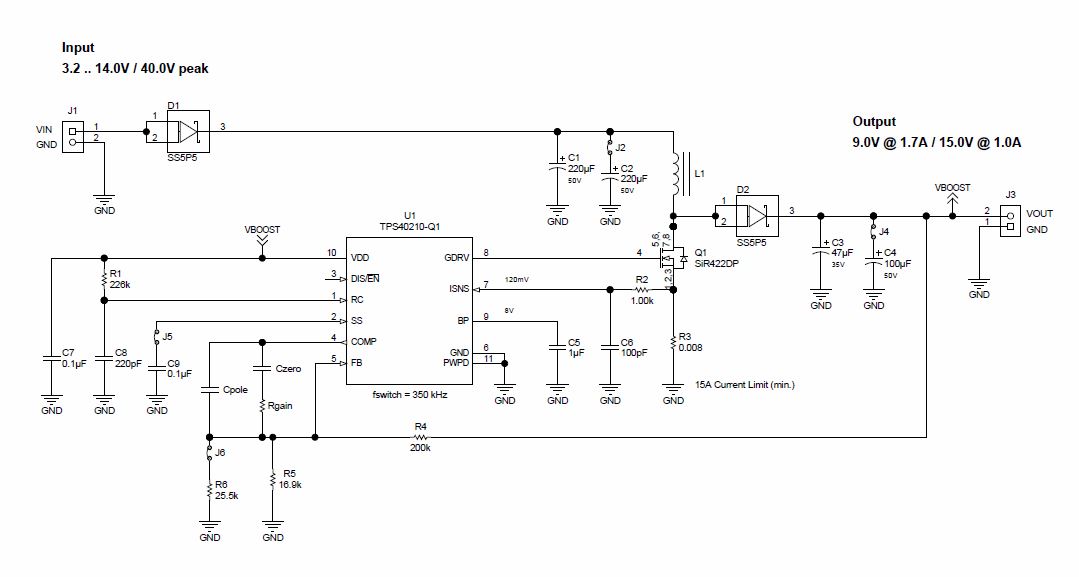
Practically any boost controller which can handle the voltage ratings and fulfils the specification regarding temperature and automotive qualification can be used. Texas Instruments’ TPS40210-Q1 is an option for this kind of application and the circuit shown in Figure 3 is the reference for the measurement results and comparisons. If the power demands are getting higher, a synchronous booster like LM25122-Q1 can be a better alternative. The diode is replaced by a FET and the 100% bypass operation mode reduces these losses significantly.
Figure 3 - pre-booster schematic
The second part of this feature provides guidance on proper part selection of all relevant components. It also shows the reaction of a pre-booster on a cold crank test pulse and the impact of its error amplifier. Read part 2.
The final part demonstrates the differences between operation modes and the influence of the inductance and capacitance on performance. Read part 3.


