Heat dissipation by baseplate-cooled solution to power supply
Since the advent of the digital age, electronic products have been asked more high-efficiency, multitasking, and lightweight. Such devices require to pack more functionality in a small space to bring consumers more convenience. The various applications can be witnessed in telecommunication, industrial equipment, medical device, or consumer electronics.
What is baseplate-cooled design?
In many applications, system developers require to assess the cooling efficiency in the development phase of the product. The internal temperature not only has considerable influence on product performance but also might lead to safety-related problems.
Power supply, for example, as drive to activate the product will generate the amount of heat energy. Once thermal energy cannot efficiently output to the outer device, it will likely damage the components of the power supply. The heat dissipation of power supply thus becomes one of the existing challenges that developers should tackle it.
When the products are loaded with more components, how to deploy the internal circuitry along with a suitable power supply within the space constraints has also caused great concern to developers.The optimal design for the thermal management and space saving is thus a must. In the light of the above issues, a baseplate-cooled and miniature power supply would be the reliable application.
Out in the market, one example that might solve the problems is CFM260S baseplate-cooled power supply from Cincon Electronics. Unlike the common power supply, the series is designed with a principle of forced convection due to its baseplate cooling solution.
Figure 1 illustrates the thermal dissipation is unevenly distributed to the outer edge of the power supply. However, Figure 2 shows a principle of the baseplate that acts as an outlet for lowering the high temperature stably and effectively.
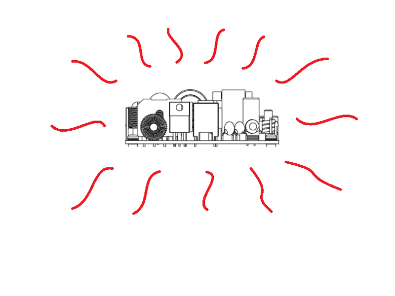
Figure 1: common power supply
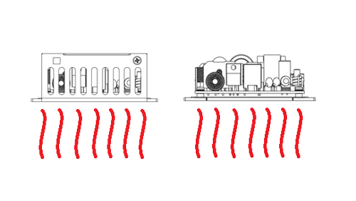
Figure 2: baseplate and baseplate with cover cooling power supply
Heat dissipation via baseplate cooling design with the convection principle
The following experiments will explore the heat dissipation through a baseplate or a baseplate with cover cooling solution. Figure 3 illustrates the two derating curves - CFM260S-B and CFM260S-C. Based on the same ambient temperature of 40℃ (natural convection), the output power of CFM260S-B is 170W, while that of CFM260S-C is 190W.
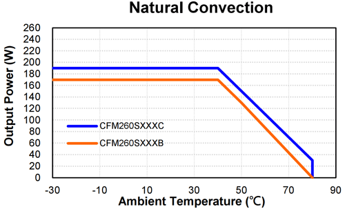 Figure 3: The derating curves of CFM260S-B and CFM260S-C
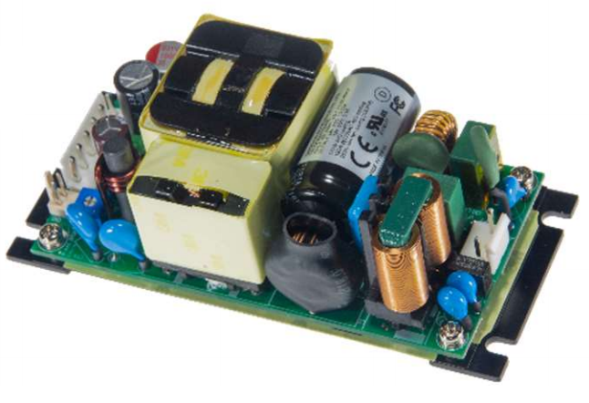 Figure 4: CFM2260S-B
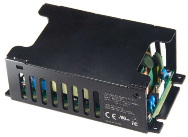
Figure 5: CFM260S-C
CFM260S, available in baseplate (Figure 4) or baseplate with cover (Figure 5) cooling solution, is installed into the device with an aluminum plate. The following experimental statistics demonstrate the adaptability and capability of two types of cooling solutions by the different evaluation criteria, such as rated power and temperature. The experimental scenarios are all set in the end-product applications.
CFM260S-B (baseplate) experiment
There is an aluminum plate (480x250x1mm) which is screwed under the bottom of CFM260S-B, as shown in Figure 6.
.png)
Figure 6: CFM260S-B (baseplate)
.jpg)
Table 1: input voltage: 115 Vac, output voltage: 12 Vdc, and ambient temperature of 40 ℃ to 70 ℃ (Natural Convection)
.jpg)
Table 2: input voltage: 230 Vac, output voltage: 48Vdc, and ambient temperature of 40 ℃ to 70 ℃ (Natural Convection)
Table 1 and Table 2 reveal that the heat conduction adheres to the principle of a baseplate convection cooling. Based on the same ambient temperature of 40 ℃ to 70 ℃ (natural convection), statistics show that the range of components’ temperature can maintain a state of stability and reliability.
Even if the CFM260S is 12 VDC output voltage with the higher output current, it can operate well under the conditions of 115 VAC input and 70 ℃. The series with the baseplate cooling remains 155W output power.
CFM260S-C (baseplate with cover) experiment
There is an aluminum plate (480x250x1mm) which is screwed under the bottom of CFM260S-C, as shown in Figure 7.
.png)
Figure 7: CFM260S-C (baseplate with cover)
.jpg)
Table 3: input voltage: 115 Vac, output voltage: 12 Vdc, and ambient temperature of 40 ℃ to 70 ℃ (Natural Convection)
.jpg)
Table 4: input voltage: 230 Vac, output voltage: 48 Vdc, and ambient temperature of 40 ℃ to 70 ℃ (Natural Convection)
Table 3 and Table 4 confirm that the heat convection cooling via the baseplate with cover is notable. It offers an optimal thermal management. Based on the same ambient temperature of 40 ℃ to 70 ℃ (natural convection), the data demonstrate that the range of components’ temperature can be more reliable and stable.
Even if the CFM260S is 12 VDC output voltage with the higher output current, it can operate well under the conditions of 115 VAC input and 70 ℃. The baseplate-enclosed cooling solution can remain 165W output power.
Installation instruction
CFM260S can be fixed on the end system applications with screws. As Figure 9 shows, for the covered version, there are two ways of fastening the power supply with a view to offering for users more flexible options of installation.

Figure 8: baseplate of installation instruction
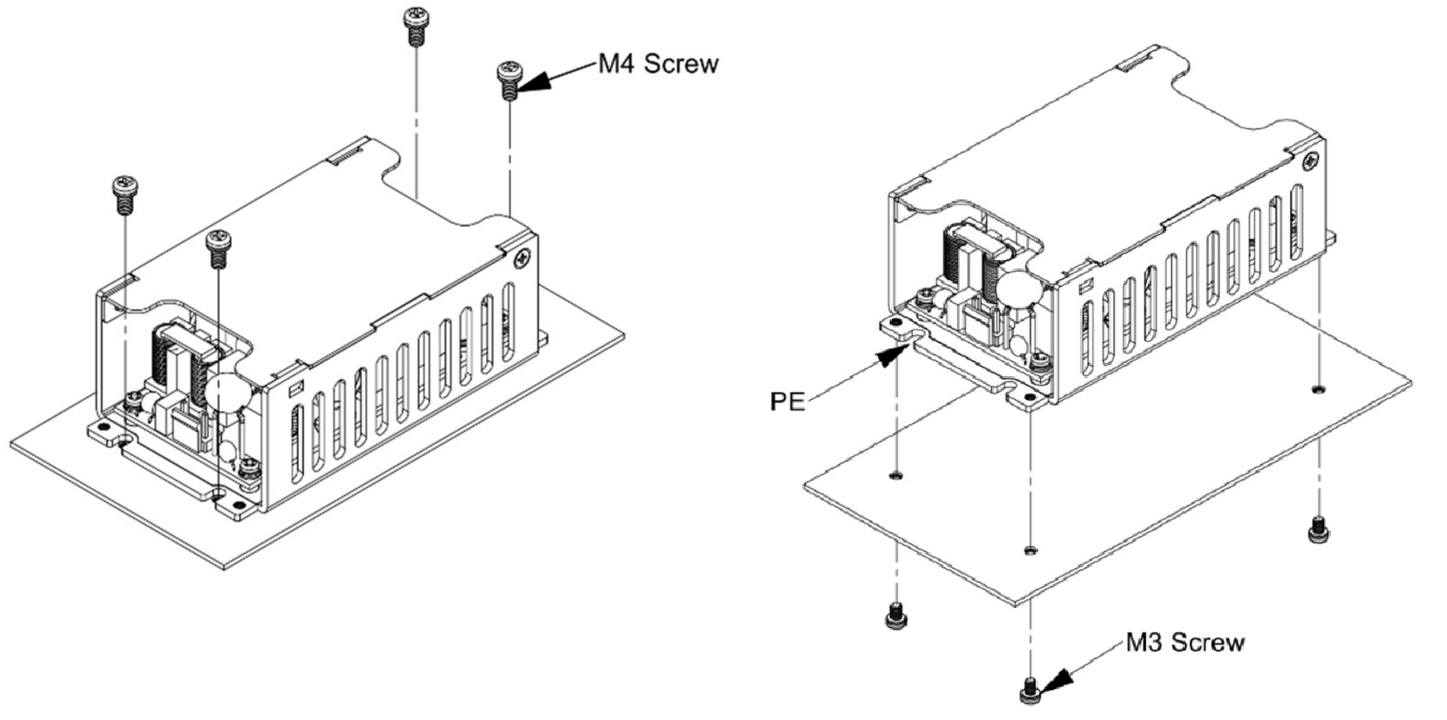
Figure 9: baseplate with cover of installation instruction
Mechanical specification
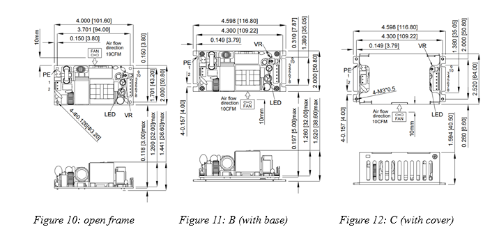
The CFM260S series features higher power density, compact size, and baseplate-cooled solution. The miniature size of 2” x 4” makes more room for the developers flexibly to employ it in space constraints. Because of its heat convection performance, even if the series is installed into the device without fan, it can operate properly and smoothly.
Additionally, the series is the structure of PFC+LLC and has a stable 260W output power. The unit supports output voltages of 12 VDC, 24 VDC, 36 VDC, and 48 VDC. Efficiency up to 93.5% can reduce the amount of power loss, to the extent of thermal decrease. To be more specific, for system developers, these features bringing added value include cost optimisation, the facilitation of the development phase, and size reduction.
Moreover, the CFM260S supports the additional 12 VDC fan output with a protection. If the system detects the fan’s malfunction or short circuit, the protection will be activated. However, it won’t influence the main output of the power supply. As Figure 13 (forced air flow curve) shows, the CFM260S series could work at 260W with a fan. Regarding whether to employ this series with fan, it depends on the developer’s need.
Generally, the thermal management is the key determinant of the lifespan of the power module. The CFM260S series offers different conduction cooling assistance, such as baseplate, baseplate with cover, or either one connected with a fan. The various choices give users more flexible cooling strategies.
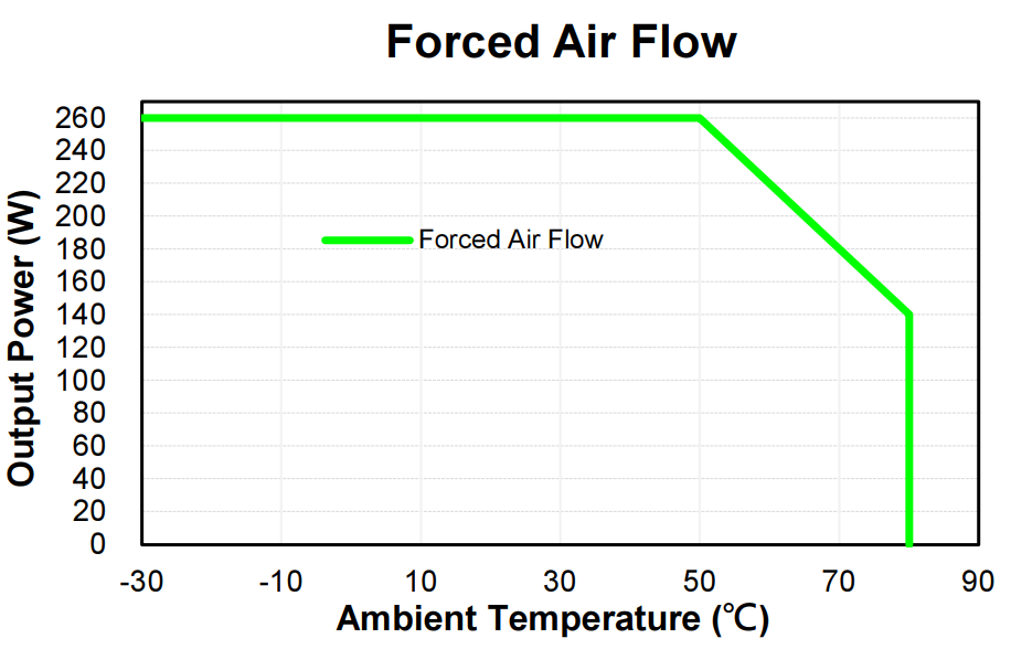
Figure 13: forced air flow curve

