Developing cost-effective DC/DC technology for 48V
European car manufacturers - and their OEM suppliers - are struggling to develop the most cost effective and efficient DC/DC converter to allow the renovated strategy of the 48V battery conversion gain space in the automotive market. Will this strategy succeed? By Davide Giacomini, Product Management & Application Director, International Rectifier.
In the late 1990s an attempt to adopt 48V batteries failed, because at that time the industry wasn’t prepared to convert all mechanic and 12V systems. In hybrid vehicles it makes much more sense; 48V lithium batteries deliver more energy per kg which allows power-consuming functions such as the power steering, starter alternator and brake pumps to be electrified and simplified. Even traction for parking or cruising can be derived from the 48V line. However this means the 48V line has to be available all the time and for this reason the main alternator is now supplying the 48V directly, while the 12V supply needed by some low power applications - such as the radio, infotainment and dashboard instrumentation - must now be generated with a DC/DC converter.
Two strategies exist; a decentralised 48/12V converter, where every 12V supply is locally generated and there is no need of an additional 12V battery, and a centralised 48/12V converter with or without additional 12V lead-acid battery. The industry appears to favour the second solution and in most cases a 12V battery is still present; in this case the DC/DC converter is required to handle bidirectional energy flow at a power level from 300W to 3 or even 5kW, which cannot be managed with a simple single phase topology but needs a multiphase configuration.
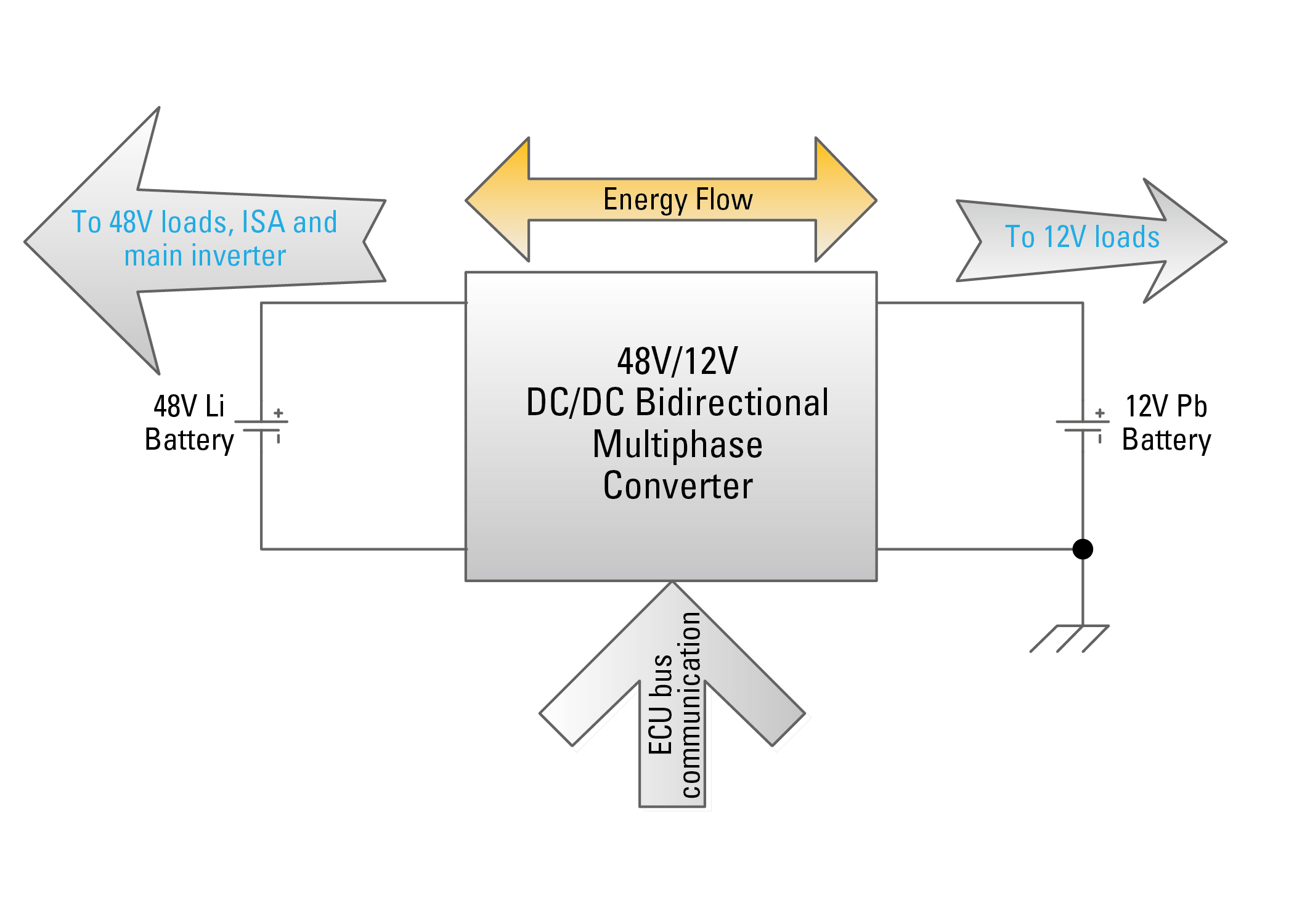
Figure 1 - General convert system block schematic
The centralised solution uses an inverter of quite high power, so far the industry is looking to support a total output current of around 200A at 12V in step-down mode, this means a maximum power output of around 2.5kW. The same power level is required in the boost mode, when the energy is taken from the 12V lead acid battery and reversed to the 48V Lithium Ion battery, the only difference is that this mode of operation is usually required for just a few tens of seconds while the normal working mode remains the buck mode. Figure 1 shows the general block schematic, the converter has to manage the energy flow between the two batteries and the conversion direction is decided by the ECU of the car based on the car utilisation condition and battery status feedback from the converter.
Closely monitored
Monitoring becomes an important part of this converter architecture and partly because of this digital control is displacing more common analog control. Its flexibility to control phases according to the total current output needed by the load offers huge savings in switching losses. All architectures must cater for maximum power output, but for about 70% of the time the converter will be working at around 30% of its power or less; dropping phases during operation is not easy for an analog solution, but for digital controllers it is, while automatically recalculating the phase rotation between the remaining phases.
In these types of multiphase converter the energy flow is only in one direction, the 12V input comes from the so-called silver box unit inside the computer or the server and the load is the CPU, sinking high current with high load transients and frequency. The main challenge of these types of converters is to maintain the CPU voltage into the specified voltage window of usually 100-200mV despite the load transients, which may reach 200A at around 100A/μs variation on the power supply output.
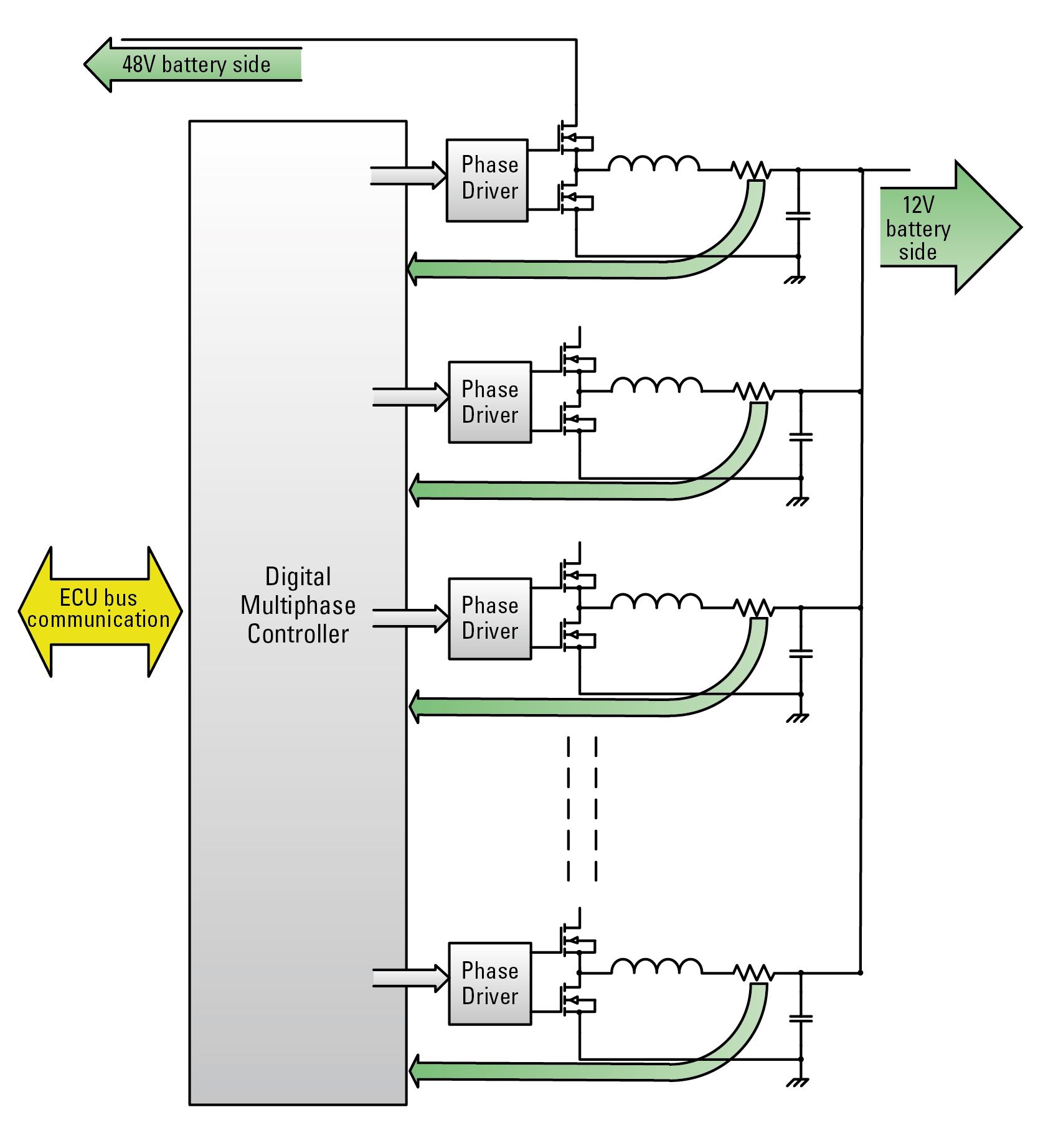
Figure 2 - 48/12V converter schematic
The schematic for a 48/12V automotive version of this multiphase solution is shown in Figure 2. The main differences and consequences of this topology are that the input and output voltages are higher - 48V Lithium Ion and 12V lead acid batteries - this means that higher breakdown voltage components need to be used, with higher cost. Also, bi-directionality is needed to allow energy balance between the batteries during operation of the hybrid car, so the algorithm embedded in the digital controller should include both. Lastly, full telemetry is needed, including input/output current and voltages.
The two batteries will also have different charging/discharging characteristics and it is necessary in both cases to control the current sink to and source from them. This can be accomplished only by a precise current sensing scheme that can read, in real-time, the current from a sensing resistor or other sensing element. The DC value must be known and an easy solution calls for a Hall-effect or sensing resistor solution, however the first reveals to be quite expensive while the second requires a good level of precision and signal processing since it cannot be dissipative and it carries a common mode of 12 or 48V across the mV measurement value.
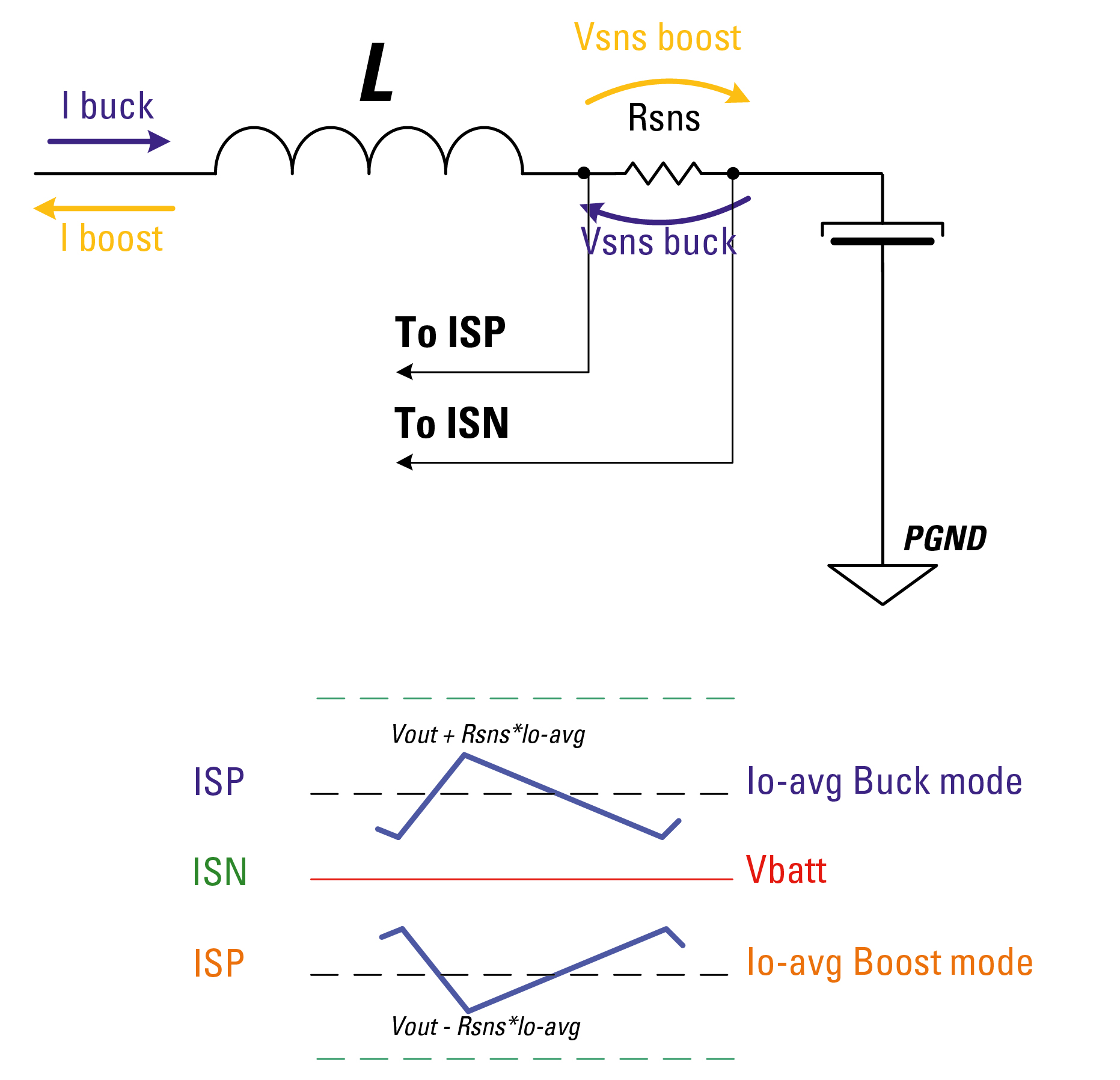
Figure 3 - Current sense signal around the Vbatt voltage
Precision of the current measurement is required to be around 1%, resolution of the measurement is usually required to be on the ±0.5A for the 12V side with ±200A total output current and ±0.2A on the 48V side with about ±50A total current. Another challenge in the current sensing is to measure current flow in the two directions since the current will be flowing in or out of the batteries based on the operation mode. This means that the signal out of the sensor will be positive or negative around the common mode, as shown in Figure 3.
The current information and its biasing position have to be correctly reported to the digital controller input to allow operation in the two different modes. The battery voltage can vary quite a lot in the car, due to sudden current consumption, load transients and overcharge. The reason for operation down to 0V is not very clear, since both types of batteries are actually dead if their voltage drops below about 60% of the nominal value, furthermore this very low voltage requires all current sensing structures to be able to withstand this large voltage variation. Particularly in the case of a resistor current sense and related differential amplifier, the very sensitive inputs of this last has to be able to withstand a very large input voltage common mode without being damaged during operation and typical qualification stress test like the Pulse 1 commonly used in the automotive environment (Figure 4).
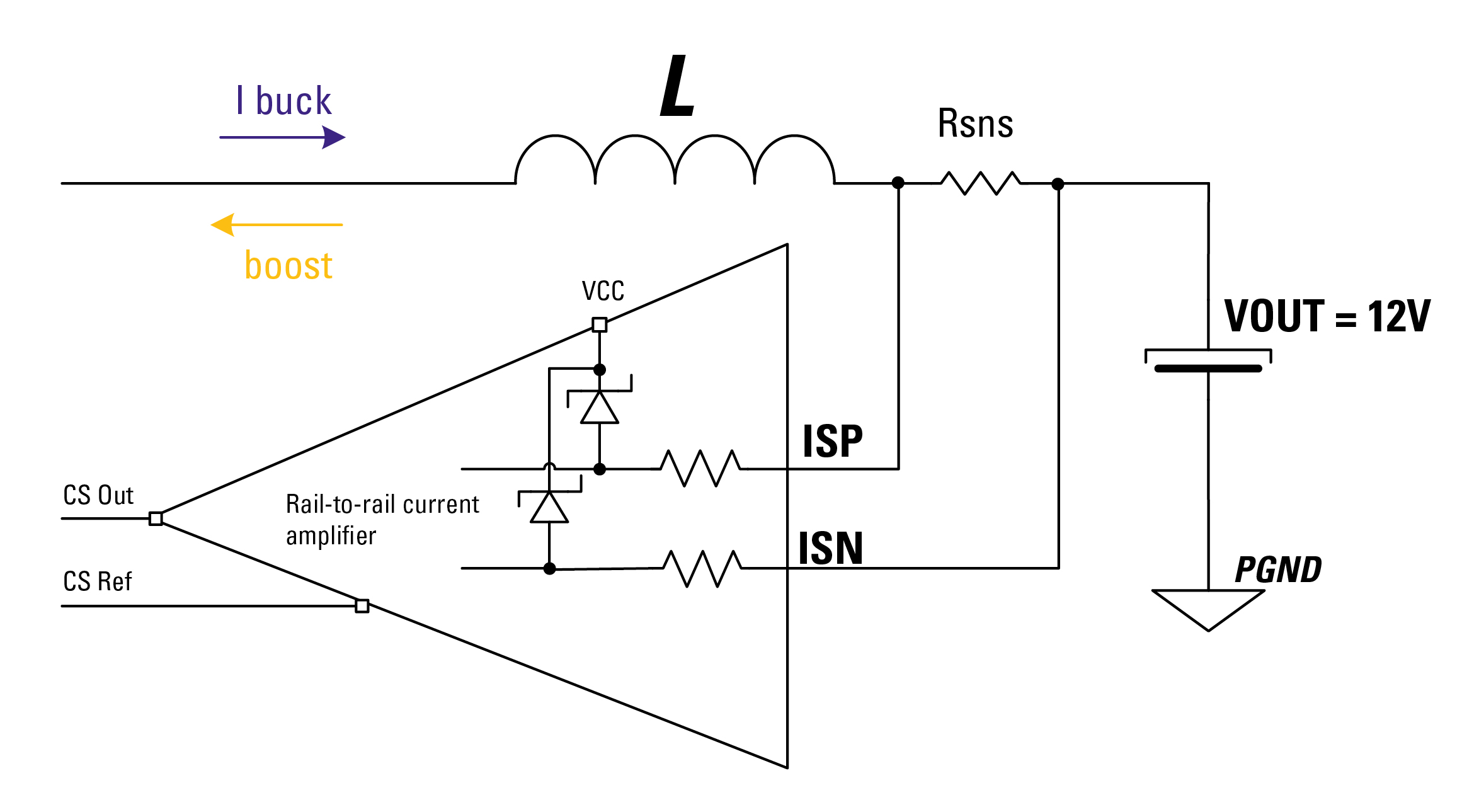
Figure 4 - Current sense amplifier protections and requirements
Last but not least, in many circumstances batteries must include a constant current limitation to avoid overheating their cells, therefore the converter must also work in constant current mode and adapt his output voltage to the battery condition. This current value may even change with the age or temperature of the battery for optimum control and it is required to be updated on the fly during normal converter operation. This is not easy at all with analog controllers and a programmable digital controller is instead appropriate.
First for automotive
Taking into account all these issues a new chipset for automotive 48/12V is being developed by International Rectifier, the new chip-set comprises a multiphase digital controller and a new gate driver with current sensing amplifier. The AUIRCT1000Q digital controller is the first ever developed with the Automotive market as a target, it derives from a long history and experience of controllers for computing application. This device addresses all the problems identified here and adds more functionalities. It can control a maximum of eight phases for better, more defined phase number optimisation with current output, the suggested configuration calls for around 300W per phase so that the higher equivalent switching frequency will allow lower output capacitance and ripple, on the other hand it will also allow faster reaction times during load transients. Both control algorithms are embedded, phase add/drop and shedding is automatic or can be decided via the serial line and all parameters can be stored once the set-up configuration has been frozen, using the internal MTP.
The AUIRS2013S gate driver has been developed to be used in conjunction with the AUIRCT1000Q or any other digital controller with tri-state PWM output and analog input for current and voltage sensing. This device solves issues around current sensing; the internal differential OpAmp can read the sense resistor voltage dropout along a large common mode voltage from 0V to above the battery level and it is internally protected from high voltage spikes coming from the sensing lines. Its output provides a positive or negative signal around an internally generated 1.25V level which is then sent to the digital controller as a reference point for the ADC input of each phase current sense. A current signal above the 1.25V indicate a buck operation while below indicates a boost operation. This device also accepts a three state PWM input to allow easy phase add/drop during operation at variable output current.
The technical challenges of implementing a bidirectional DC/DC converter for the emerging automotive 48/12V applications are new to the market of power electronics and especially to automotive OEMs. Today’s solutions based on existing components availability are forcing engineers to solve the main problems using complicated and expensive electronics in quite large schematics. IR and other electronics component manufacturers are getting ready to meet the new market requirements by developing dedicated parts that will address the new topology challenges and allow a cheaper and more reliable implementation of these converters, finally speeding up the adoption of this new 48V voltage standard for car applications.


