Considerations for integrating high voltage power modules into critical applications
The design-in of high voltage (HV) power modules presents a number of challenges, some of which are application-dependent, says Hafiz Khalid senior high voltage product manager, XP Power
Through discussions with design engineers over a period of years, it is apparent that the primary challenges defining the HV module requirements correctly, ensuring that the HV power converter is accurate, design of any additional HV circuitry needed in the application and the ease to which the HV module can be integrated into the final design.
Accurately and comprehensively defining requirements is a critical first step in the design process and needs to cover all major parameters of the module that will be relevant to the application.
Designers must know the available input voltage and any control signals that are available (or are able to be generated where necessary). The input voltage accuracy is important as it defines the necessary line regulation for the module as well as protection requirements. Understanding the control signals required to operate the module correctly and safely is also important, as is knowing what monitoring outputs are available from the module to use to enhance the application.
Clearly, the load must be known and understood. Many applications present a complex (non-resistive) load which will define requirements for the module, along with the basic parameters such as voltage, current and polarity needs. As an example, a typical photo-multiplier tube may require 1200V DC at a few µA of current.
Considering the environment
Depending upon the application, there may be specific environmental conditions including elevated operating temperatures or high levels of humidity that must be considered. Designers must understand where the application is to be used as well as where in the application the HV module resides.
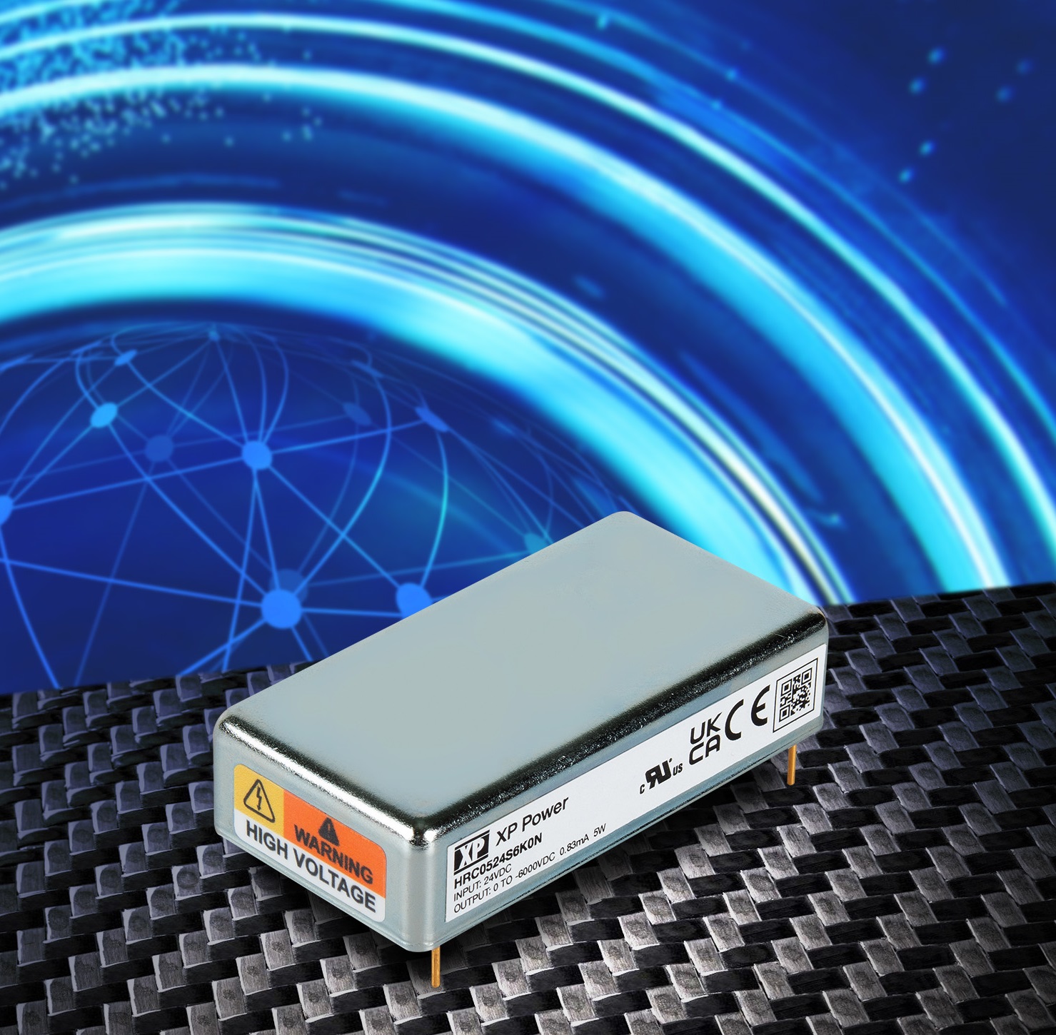
 Figure 1: The HRC05 is an example of a high voltage module in a miniature package.
Few modern applications have a lot of space available, which restricts the size available for the HV supply in the overall application - especially in small desktop and handheld applications where size becomes very critical. Even in applications that offer more space such as semiconductor fabrication, inspection tools, and analytical instruments the focus is generally to make them as small as possible, allowing more functionality in the same space.
Meeting standards
Agency approvals become critical where the end application is within an industry segment that has one or more regulatory approval requirements. As an example, UL/IEC/EN 61010 is a requirement for the analytical instrument market and there are many other for different applications where certain approvals are required. Selecting a module that is pre-approved to relevant standards saves time and cost in obtaining end equipment approvals.
Accuracy of the HV power converter can be affected by other variables including variation in the input voltage, loading conditions, operating temperature, and a number of other environmental factors. Key parameters to consider for any HV module include the output voltage tolerance which defines any variation from the specified output voltage and the setpoint accuracy that confirms the ability of the module to achieve the set point using the control voltage.
Line and load regulation which specify the ability of the module to maintain the output voltage within the regulation specification based on the variation in the input voltage and the load are another key consideration as is ripple and noise that defines any residual AC signal on top of the DC high voltage supply.
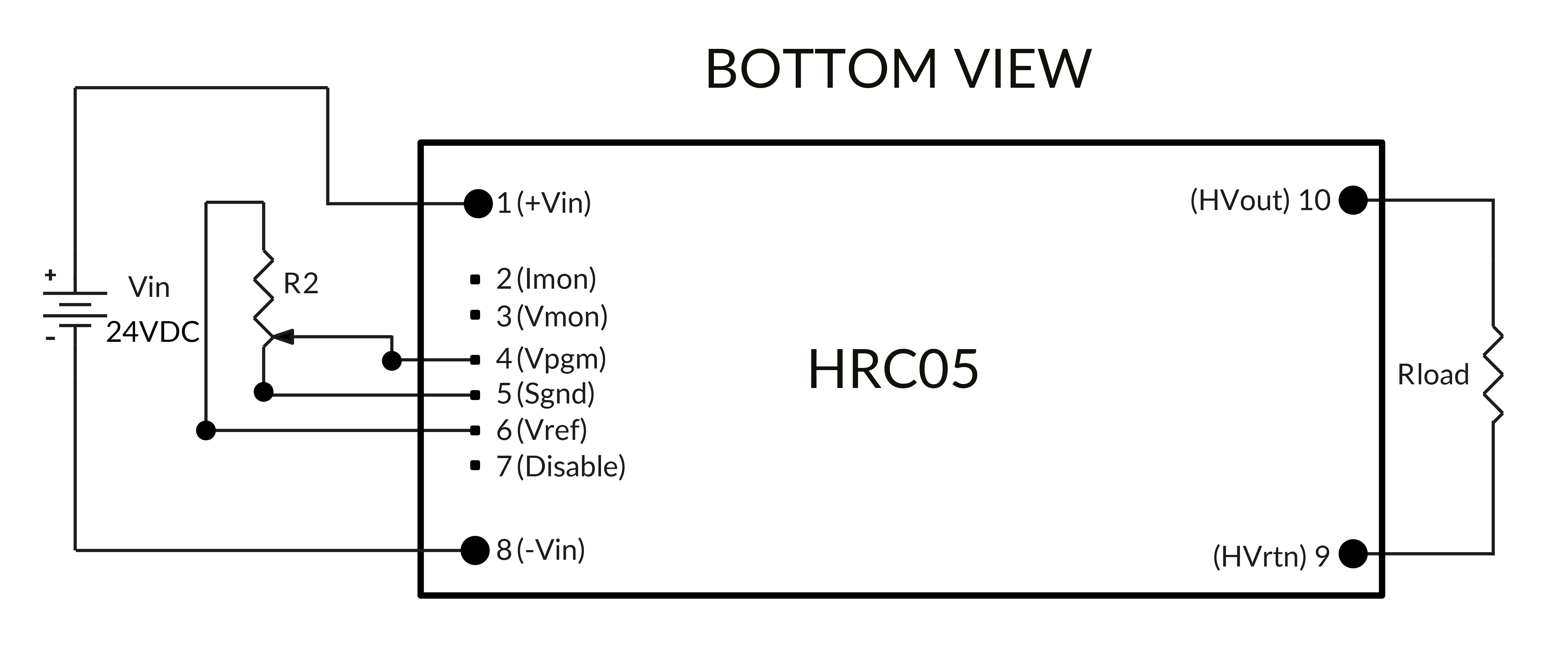
 Figure 2: Block diagram of XP Power’s HRC05 integrated module.
Where output control exists, the transfer function between the control voltage and the output voltage may be non-linear which would have an impact on the application.
In certain applications, especially analytical instrumentation related, the output stability over time is important to ensure repeatability throughout an experiment. This is particularly important in mass spectrometry where sensitive equipment is powered for a period of several hours. Some HV modules can be affected by changes in ambient temperature. Fortunately, long-term drift and temperature co-efficients are usually specified on datasheets, allowing designers to account for them.
Designing the circuitry around HV
Designing a HV circuit board requires attention to many details that are not relevant when designing a low voltage or digital circuit board. A particular application may necessitate components / circuitry around the HV module which becomes challenging, especially on the secondary / HV side. Some of the important considerations for HV design are :-
Proper creepage and clearance distances from low voltage circuitry;
No ground planes in the high voltage area;
Avoiding sharp edges on the pads on the circuit board;
No silk screens in the vicinity of high voltage;
No plated holes in the high voltage area;
Slots in the board if needed to provide isolation;
Conformal coating and other insulating materials, if needed.
When specifying components for use in HV electronics, designers must consider the voltage / power ratings and any necessary derating as well as voltage / temperature coefficients and the thermal performance of the components themselves.
Due consideration must also be given to the electrical and mechanical aspects of HV module integration into an application. In many cases, useful features are already incorporated in the HV module that can simplify and shorten design times.
Many HV modules incorporate under- and over-voltage protection on the input side that protects the unit from glitches on the input line. There may also be protection that prevents mis-programming of the control voltage, which prevents damage to the HV module.
On the secondary (output) side, arc protection prevents damage due to arcing events in the application which can have severe consequences. Also, over-current and short circuit protection provide safety for the module and the application in case of a fault condition that could force the HV module to operate beyond its specification. Similarly, thermal shutdown protects the module if its temperature rises beyond its specified operating temperature range. Both latching and non-latching thermal protections exist, however the HV module normally recovers after the over-temperature condition has been removed.
For the signals used to control and monitor the HV module, the digital compatibility of these signals defines the circuitry required to control the high voltage. If the signals are DAC-compatible, then controlling the voltage becomes much easier many modules have that feature available.
Often, general lab equipment is not capable of measuring the voltages present in HV modules as they are limited to 1kV DC. Some modules have digital compatible monitor signals that simplify measurement for the designer as no instrument is needed.
Physical considerations
At a practical level, there are a number of things that must be considered so that any HV module can be physically integrated into an application. In many cases (and especially with modules) the input and output connections will be solderable PCB pins. However, other connection types may be used. The number, position and type of pins is also important to know and consideration must be given to safe routing of HV traces to ensure compliance with safety requirements such as creepage and clearance.
The physical size of the module is important, both the PCB footprint and height. The weight is worth consideration, especially in applications which may be subject to shock and / or vibration, however infrequent. If additional heatsinking is required on the module then this must be factored into any size / weight considerations and the means of affixing the heatsink must be compatible with production processes.


