Mixing it up
Reporting for ES Design magazine, Steve Rogerson looks at the methods for testing and verifying PCB layouts containing mixed-signal and analogue components.
There is a tendency when talking about testing and verification to consider the domains of digital and analogue as separate compartments. There are those who test analogue circuits, and they have their own methods and preferences, and then there is the digital world, where they speak a different language and also have their own ways of doing things.
But the challenge comes when a PCB has a mix of analogue and digital components, which not only interact with each other but where one affects the performance of the other. A high-speed digital pipe can cause interference to nearby analogue signals, for example. Yet, until recently, the testing of analogue and mixed signal parts has been carried out separately with a certain amount of hit and miss when they were mingled. Often, some kind of iteration process was involved.
However, modern design and test tool makers are trying to overcome that limitation, to a degree, by at least giving the user a unified view even if the databases underneath are still separate.
“It has been a trend in the industry where you tend to bundle things into digital and analogue buckets but when the two interact, things become a lot more challenging,” said Brad Griffin, Product Director at Cadence Design Systems.
He said that traditional tools were designed and positioned to solve digital problems yet the digital signals could have an influence on the analogue side and calculating that was often a manual process, albeit with help from some tools. Nevertheless, the traditional process for checking, say, signal integrity was far from ideal and more than a little cumbersome, even when using analogue simulation tools such as PSpice.

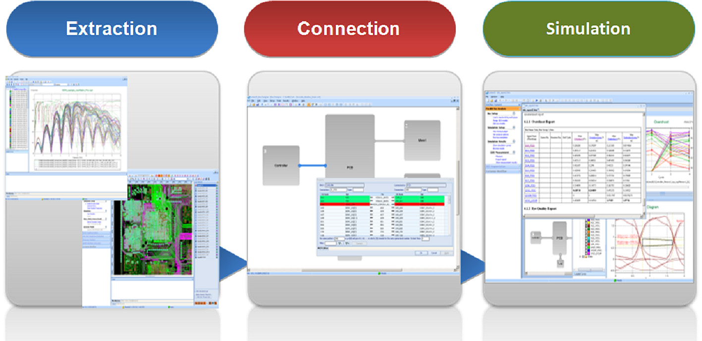
Extracting the pertinent signals from the PCB (analogue and digital), connecting them to other fabrics if necessary (flex cables, packages and so on) and then simulating and interpreting the results (crosstalk between digital and analogue signals)
“The problem is that these types of tools are standalone,” said David Wiens, Marketing Development Manager at Mentor Graphics. “So if you want to do a circuit simulation, you go into PSpice or similar and recreate your schematic using that. You then have to go back and make the edits into the original schematic. There is an inherent discontinuity in what you are doing. You could be deploying the best simulator on the planet, but if you don’t get the results of that back into your schematic, you are wasting your time.”
Griffin said that testing the signal integrity separately brought in the difficulty of checking whether the analogue circuits were completely isolated or at least the noise from the digital was below the acceptable level.
“As long as it meets the minimum criteria, that gives the engineer the confidence in the simulation phase,” he said. “But the traditional way to fix the problems is to spend time in the analogue tool. If you figure you have a problem, you might play a what-if game and move traces around and change the lengths of transmission lines to see if it works. But ultimately, you have to go back to the implementation tool and make the changes to the layout and then re-simulate. That is the traditional way.”
Closing the loop
But tool vendors are now tackling the problem of making the loop between the digital and analogue tools smaller rather than having them in completely different domains. One way is to integrate the simulation tools with a light version of the implementation tools so the engineer can play with the design to see if changes work before passing it back to the implementation designer.
“We have made the tools so they live within the same cockpit,” said Griffin. “They live side by side. You zoom into the layout and it zooms in onto the analysis and vice versa. The databases are still separate but the user sees them as totally integrated.”

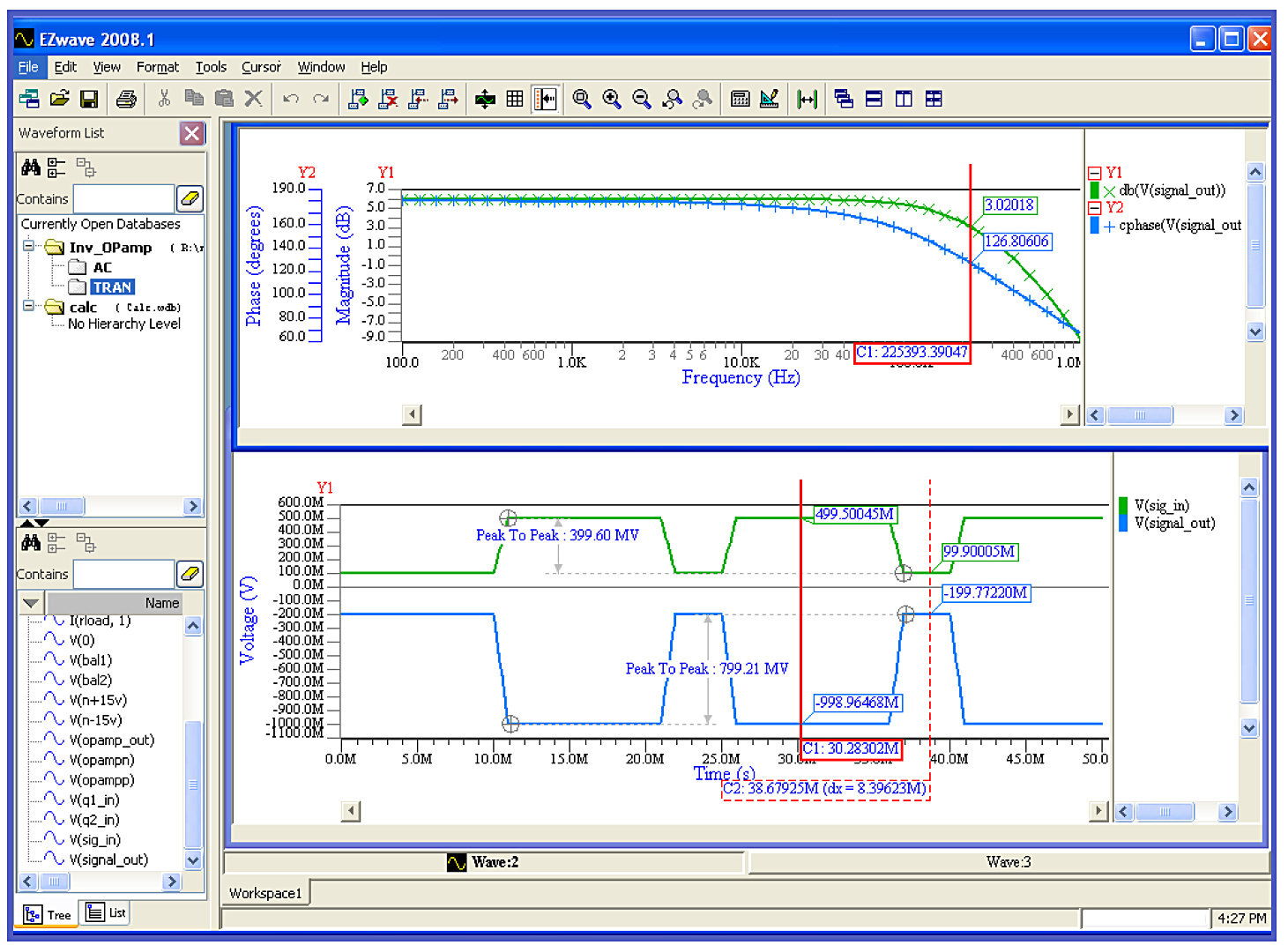
Customise the display of the simulation results for clearer understanding using an intuitive viewer
Wiens said that Mentor’s approach was to use the same tools for both aspects.
“You do the simulation and the PCB design in one schematic,” he said, “so if you make changes from the simulation they are baked into the schematic for the PCB layout.”
He was also critical of the ability of tools such as PSpice. “We acknowledge that a lot of people use PSpice,” he said, “but there are levels of simulation that PSpice just can’t handle. We have simulators that can handle full mixed signal and digital simulation, and this is all functional simulation.”
The other problem is being able to simulate all the possible conditions that a circuit might face, and here often a compromise has to be made between the time spent in simulation and the quality of the product when it comes to market.
“With enough horse power, you can test anything,” said Wiens, “but there is always a time crunch. There is a trade off. How much simulation do I want to do and when do I cut off and do a design?”
Griffin agreed. “There is a compromise between time to market and quality,” he said. “How much time is reserved for this type of verification in the go-to-market cycle? If you are designing a smartphone or tablet, you are on a strict time to get your product to market. You don’t have two to three months for verification.”
One way to speed up this process is to do a lot of the analysis at the start of the design using what-if scenarios and then putting these into the design tools as constraints. For example, in the case of high-speed digital lines interfering with analogue signals, a constraint could be to set a minimum distance between the different lines. Then if at any time during the layout the lines become closer than that, an alert is triggered.

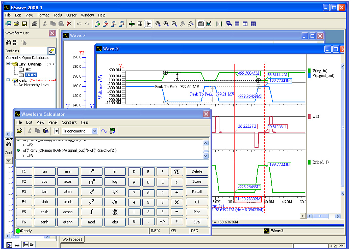
Use built-in measurement tools and the waveform calculator to perform post-processing analysis of the results
“If you don’t do this type of thing up front,” said Griffin, “then you will go to market with products that are low on quality or you will miss your time to market. If you do it, then the detailed analysis should only bring in a few tweaks.”
PCB design
An area where PCB design differs from chip-level design is that almost all is now done using commercial tools whereas with chip level there are a number of companies who design their own tools. These days, the PCB design tools available are at the sort of level that suits just about all comers.
“If you are a big company, you might have your own tools, but really those days have gone,” said Griffin. “It is very difficult to manage that type of tool development when there are companies such as us developing very sophisticated tooling. It is to their benefit to use a commercial tool.”
One of the most common areas where mixed-signal testing comes into play is in military and aerospace, where there are digital and analogue signals and RF as well.
“When you do mixed analogue, digital and RF, it is not just simulation, it is now about laying out a circuit so the three domains do not interfere with each other,” said Wiens. “The noise behaviour here can be quite a lot higher and the physical verification becomes more important.”
This is also now an issue in smartphones where fitting the various circuits into tight spaces often involves bending wires back on themselves. Keeping the RF and other signals apart can be a nightmare in such a constrained area.
The automotive market is also proving a mixed signal challenge with the spread of infotainment systems. And in medical, the situation arises from handheld devices and even pacemakers right up to large pieces of MRI equipment. The industrial market, even though the circuits are often simpler, also sees a mix of digital and analogue in areas such as motor control, and here the circuits themselves are installed into often an inherently noisy environment.
However, the message for whatever market is to start the test and verification process early in the design cycle so that most of the problems when it comes to simulation will already have been solved. That way it is possible to be on time and maintain high quality.


