
Schematic capture software for electronics engineers
Schematic capture software is an indispensable tool for engineers engaged in the creation of electronic circuits and systems.
This software facilitates the process of designing and documenting electronic circuits by allowing engineers to create and manage schematic diagrams digitally.
What is schematic capture software?
Schematic capture software, also known as schematic entry software, is a specialised application used to create electronic circuit diagrams. These diagrams are essential blueprints for designing and understanding electronic circuits, serving as a visual representation of the components and connections within a circuit.
The primary function of schematic capture software is to provide a user-friendly interface for drawing and managing schematic diagrams.
Key features typically include:
- Component libraries: These libraries contain a vast array of pre-designed electronic components, such as resistors, capacitors, diodes, transistors, and integrated circuits, which engineers can readily incorporate into their designs.
- Symbol creation and editing: Engineers can create custom symbols for components not found in the standard libraries or modify existing symbols to suit specific design requirements.
- Connectivity and netlisting: The software ensures accurate connections between components and generates netlists, which are essential for further stages of the design process, such as PCB layout and simulation.
- Design rule checks (DRC): Automated checks help identify errors and ensure that the schematic adheres to predefined design rules, reducing the risk of issues in later stages of development.
Integration with other tools: Schematic capture software often integrates seamlessly with PCB layout tools, simulation software, and other engineering applications, facilitating a smooth workflow from schematic design to final product.
Who uses schematic capture software?
Schematic capture software is primarily used by electronics engineers and designers involved in various stages of electronic product development. This includes:
- Design engineers: They use the software to create and refine circuit designs, ensuring functionality and reliability.
- Test engineers: They utilise schematics to develop testing protocols and identify potential points of failure in a circuit.
- Research and development teams: These teams rely on schematic capture software to prototype and experiment with new electronic concepts and technologies.
- Educational institutions: The software is also widely used in academic settings to teach students about electronic circuit design and analysis.
The use of schematic capture software offers numerous advantages that make it an essential tool for electronics engineers:
- Accuracy and precision: Digital schematics reduce the likelihood of errors compared to hand-drawn diagrams, ensuring that designs are accurate and reliable.
- Efficiency: The software streamlines the design process, allowing engineers to create and modify schematics quickly and efficiently.
- Documentation: Schematic diagrams serve as detailed documentation for the design and manufacturing process, aiding in troubleshooting, maintenance, and future upgrades.
- Collaboration: Digital schematics can be easily shared and reviewed among team members, fostering collaboration and communication within development teams.
- Integration: The seamless integration with other design tools and software ensures a coherent workflow, from initial design to final production.
Schematic capture software is a vital component in the toolkit of electronics engineers. It enhances the accuracy, efficiency, and collaborative potential of electronic circuit design, making it an indispensable resource in the development of modern electronic devices and systems.

Featured products
MAX17793
Analog Devices Inc.
3V to 80V, 3A, High-Efficiency, Synchronous Step-Down DC-DC Converter
| SKU: | MAX17793 |
|---|---|
| Stock: | 9316 |
| Cost: | $3.64 |
MAX22516
Analog Devices Inc.
IO-Link Data Link Controller with Transceiver and Integrated DC-DC
| SKU: | MAX22516 |
|---|---|
| Stock: | 8000 |
| Cost: | $5.42 |
Product Spotlight
102991834
BeagleBoard

Single Board Computer (SBC), BeagleY-AI
AM67A BeagleY-AI Jacinto 7 AR...
| SKU: | 2820-102991834-ND |
|---|---|
| Stock: | 206 |
| Cost: | $56.24 |
SC1110
Raspberry Pi
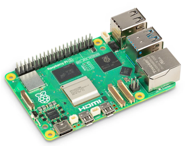
Raspberry Pi 5 2GB
The Raspberry Pi 5 2GB model represents a leap for...
| SKU: | 2648-SC1110-ND |
|---|---|
| Stock: | 0 |
| Cost: | $38.33 |
AKX00069
Arduino
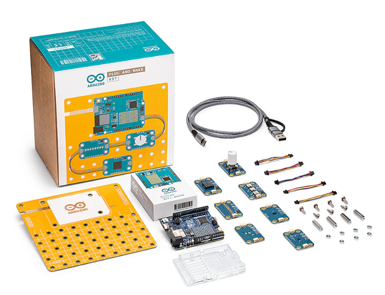
Arduino Plug and Make Kit
The Arduino Plug and Make Kit features the ...
| SKU: | |
|---|---|
| Stock: | 968 |
| Cost: | $66.97 |
300361-0011
Molex
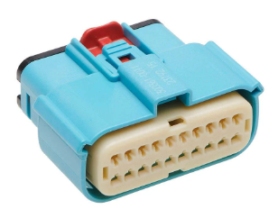
MX150 Mid-Voltage MatSealed Female Connector Assembly, Dual Row, 20 Circ...
| SKU: | |
|---|---|
| Stock: | 280 |
| Cost: | $2.51 |