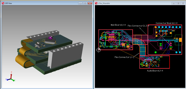
PCB flow addresses increasing complexity of advanced systems designs
The first phase of the Xpedition PCB flow to address the increasing complexity of today’s advanced systems designs has been announced by Mentor Graphics Corporation. The increasing densities of electronics products are forcing companies to develop highly compact system designs with more functionality, and at lower costs.
To efficiently manage the density and performance requirements for advanced PCB systems, the Xpedition flow provides advanced technologies to enable design and verification of 3D rigid-flex structures, and to automate layout of high-speed topologies with advanced constraints.
“Our customers are industry leaders developing the world’s most advanced electronics systems. They require access to technologies that enable deployment of advanced technologies and techniques, from design for high performance, advanced packaging, growth of rigid-flex, and higher speeds and densities,” said AJ Incorvaia, Vice President and General Manager, Mentor Graphics Board Systems Division. “To deliver the latest Xpedition Enterprise flow, we have partnered with our customers to address their strategic initiatives to manage increasing complexity, increase organisational collaboration, drive greater end-product quality, and facilitate enterprise IP management.”
Managing advanced rigid flex design complexity
Flex and rigid-flex PCBs are now found in all types of electronics products, from small consumer devices to aerospace, defence and automotive electronics where high reliability and safety are critical. The Xpedition rigid-flex technology enables a streamlined design process from initial stack-up creation through manufacturing.
Engineers can design complex rigid and flex PCBs in a fully supported 3D environment (3D design and verification—not just a 3D view), resulting in a correct-by-construction methodology for optimum reliability and product quality. 3D verification ensures that bends are in the right position, and elements on the board do not interfere with folding; this can be reviewed early in the design stage to prevent costly redesigns. Users can then export a 3D solid model to MCAD for efficient bi-directional PCB-enclosure co-design.
Integration with Mentor’s leading HyperLynx high-speed analysis technology enables optimisation of signal and power integrity across complex rigid-flex stack-up structures. For fabrication preparation, the Xpedition flow provides all flex and rigid information using the ODB++ common data format. This methodology eliminates data ambiguities by clearly communicating the finished board intent to the fabricator. The new Xpedition flow is the optimum solution designed specifically for flex and rigid-flex design, from conception through fabrication output.
“Mentor’s new Xpedition flow provides multiple board outlines, stack-ups, and bend areas which allow us to define a rigid flex within the design environment, and export a folded 3D step model for efficient mechanical design integration,” stated Charles Ietswaard, PCB design engineer at NIKHEF, the national institute for sub-atomic physics in The Netherlands. “The automated rigid-flex capabilities in Xpedition help us manage the growing complexities of today’s advanced PCB systems with ease, higher productivity and overall product reliability.”
For efficient rigid-flex development, key features and capabilities include:
- definition of the rigid-flex stack-up with unique outlines for each region, enabling simpler design changes than stack-up by zone. Standard flex materials (e.g. laminates, ‘embedded’ or ‘bikini’ cover layers, stiffeners, adhesives, etc.) can be included in the stack-up
- full support of flex bends to manage where and how the PCB bends, including parts placement on flex layers, flex routing, plane shape fills, tear drops and trace drops. Once bends are defined, the design can be viewed and validated in 3D to ensure there are no collisions
- powerful user interface with intuitive and simple selection controls to properly manage the design
- Electrical Rule Checking (ERC) using a customisable local rules checker and a comprehensive set of post-design checks for first-pass success
- flex-aware signal and power integrity analysis, enabling accurate modeling of interconnect as it passes through different stack-up regions
- Design For Manufacturing (DFM) validation and New Product Introduction (NPI) tools to ensure seamless PCB design to fabrication management and efficiency

Automated layout for high-speed designs
The new Xpedition release also features advanced layout automation to address increasing complexity in high-speed designs and emerging guidelines for high-end computing chip-sets. The following key functionality helps optimize designs for performance:
- tabbed routing, an interconnect geometry used to minimise crosstalk and impedance discontinuities, can be created and modified on high-speed traces
- designers can create and modify a routing strategy with sketch plans that define a path for trunks of nets, including trace shielding
- enhanced tuning enables better feedback and control during interactive editing to achieve high-speed constraints
- nets which require back drilling can be defined in layout and output for manufacturing
- engineers can import Polar stack-ups and layer mapping directly into the constraint manager to simplify design start-up
- a new user interface enables review of all design rule checks in the design for quick identification and resolution of electrical and manufacturing design violations
The new Xpedition flow for flex/rigid-flex and automated high-speed design layout is available today.


