How to deal with the high number of electronics in the automotive industry
Jeff Gruetter, Senior Product Marketing Engineer, Linear Technology Corporation, explains how high voltage synchronous buck converters with ultra-low IQ can meet the demands of new automotive designs
As the electronic component count in automotive systems increases, the amount of available space continues to shrink, greatly increasing the density of each system. All of these systems require power conversion ICs, usually with multiple voltage rails for each subsystem. Traditionally, linear regulators provided the majority of these power conversion needs as efficiency and small size were not of significant importance.
However, as the power density has increased by orders of magnitude, and many applications require relatively high ambient temperature operation, any practical heat sinking is too large to be accommodated. Thus power conversion efficiency has become critical in order to minimise the power lost as heat, driving step-down switching regulators to replace linear regulators. However, emerging automotive designs require the switching regulators to deliver very high efficiencies even with a wide variation of supply voltages, very low quiescent current and fast switching frequencies, all in a very compact, cost effective solution footprint.
Stop-start systems
In order to maximise fuel mileage while minimising carbon emissions, alternative drive technologies continue to evolve. Whether these new technologies incorporate an electric hybrid, clean diesel or a more conventional combustion design, chances are they will also incorporate a stop/start motor design. Already prevalent in virtually all hybrid designs around the world, many European and Asian car manufacturers have also been incorporating stop-start systems into conventional gas and diesel vehicles as well.
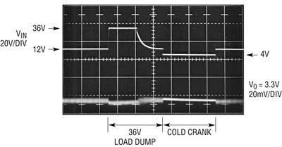
Stop/start systems create yet another challenge for power management systems. First, the battery must be capable of powering the vehicles lights, environmental control and other electronics, while the engine/alternator is off. Additionally, it must be capable of powering the starter when the engine is once again re-started. This extreme loading of the battery during start-up introduces yet another design challenge, this time electrical, as the large draw of current required to restart the engine can temporarily pull the battery voltage as low as 4V, quite similar to the cold crank voltage profile in Figure 1. The challenge for electronics arises in supplying a well regulated output just a few hundred millivolts below the input to keep critical systems running uninterrupted when the battery bus voltage is briefly below its nominal 13.8V when the charger returns to steady state.

Figure 1. LT8610 with 36V Load Dump Transient & 4V Cold-Crank Scenario
‘Cold Crank’ is a condition that occurs when a car’s engine is subjected to cold or freezing temperatures for a period of time. The engine oil becomes extremely viscous and requires the starter motor to deliver more torque, which in turn, draws more current from the battery. This large current load can pull the battery/primary bus voltage below 4.0V upon ignition, after which it typically returns to a nominal 13.8V. The electrical result to the vehicles power bus can be seen in Figure 1, but for different reasons. It is imperative for some applications such as engine control, safety and navigation systems to require a well regulated output voltage (at least 3V) through a cold crank scenario, so as to continually operate while the vehicle starts.
‘Load-Dump’ is a condition where the battery cables are disconnected while the alternator is still charging the battery. This can occur when a battery cable is loose while the car is operating, or when a battery cable breaks while the car is running. Such an abrupt disconnection of the battery cable can produce transient voltage spikes up to 60V as the alternator is attempting a full charge of an ‘absent’ battery. Transorbs on the alternator usually clamp the bus voltage somewhere between 30V and 34V and absorb the majority of the surge. However, DC/DC converters downstream of the alternator are subjected to transient voltage spikes as high as 36V as shown in Figure 1. These converters are not only expected to survive, but must also continually regulate an output voltage through this transient event.
‘Always-On’ systems need ultra-low supply current
Many electronic subsystems are required to operate in ‘standby’ or ‘keep alive’ mode drawing minimal quiescent current at a regulated voltage while in this state. These circuits can be found in most navigation, safety, security and engine management electronic power systems. Each of these subsystems can use several microprocessors and microcontrollers. Most luxury cars have over 100 of these DSPs onboard and approximately 20% of these require always on operation. In these systems, the power conversion ICs must operate in two different modes. First, when the car is running, the power supplies that power these DSPs will generally operate at full current fed by the battery and charging system. However, when the car ignition is turned off, the microprocessors in these systems must remain ‘alive’, requiring their power ICs to provide a constant voltage while drawing minimal current from the battery. Since there can be upwards of 20 of these always-on processors operating at once, there is an significant power demand on the battery even when the ignition is turned off. Collectively, hundreds of milliamps (mA) of supply current can be required to power these always-on processors, which could completely drain a battery in a matter of days.
In order to better manage these requirements, several automotive manufacturers created a low quiescent current target of <10uA for each always-on DC/DC converter. Until recently, systems manufacturers were required to connect a low quiescent current LDO in parallel with a step-down converter, and switch between the two to reduce the current draw from the battery when the car’s engine is not running. This created expensive, bulky and relatively inefficient solutions.
A new alternative
The voltage of automotive battery bus can vary from under 4V to over 40V as it is exposed to different transient scenarios. With the aggressive adoption of stop-start operation, the power bus will be subjected to low voltage transient conditions many times during an average trip. The need for well regulated voltage rails through these conditions will be of paramount importance for automotive electronics. As the growth of electronic content in automobiles continues to accelerate with ECUs used for security, safety, navigation, chassis control and engine/transmission management, so will the need for high voltage power management ICs which can offer high efficiency, low quiescent current, high frequency switching with very robust protection features and reliability.
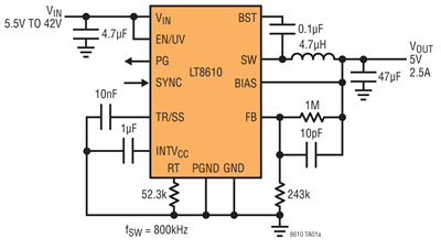
Linear Technology’s LT8610 is part of a family of high voltage synchronous buck regulators. Its 3.4V to 42V input voltage range makes it well suited for automotive applications that are subjected to both low voltage transients such as cold crank or stop-start scenarios as well as high voltage transients encountered during a load dump scenario. Its 2.5A continuous output current capability and ability to deliver outputs from VIN-200mV to 0.97V makes it well suited for many automotive rails that run directly from the battery bus. Its very compact and simple solution footprint eliminates the need for any external diodes and can be seen in Figure 2.

Figure 2. LT8610 Typical Automotive Schematic for a 5V, 2.5A Output
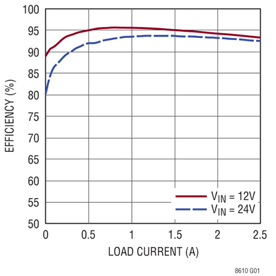
Its synchronous rectification design includes internal top and bottom MOSFETs to deliver efficiencies as high as 96%. Figure 3 shows that it can deliver over 95% efficiency when powering a 5V load from a nominal 12V input, even with a relatively high 800kHz switching frequency. This high efficiency operation minimises wasted power and eliminates the need for heat sinks even in the most space constrained applications. In electric vehicles and hybrids, this can directly translate into increased driving range between battery recharges.

Figure 3. LT8610 Efficiency Graph of Typical Automotive Schematic
Additionally, the LT8610’s Burst Mode operation reduces no load quiescent current to 2.5uA, making it well suited for always-on applications that must maintain constant voltage regulation even at no loads while maximising battery life. Additionally, a very low ripple Burst Mode operation topology minimises output noise to below 10mVPK-PK, making it suitable for noise sensitive applications. If the application requires external synchronisation, the Burst Mode function can be replaced with a pulse skipping frequency scheme.
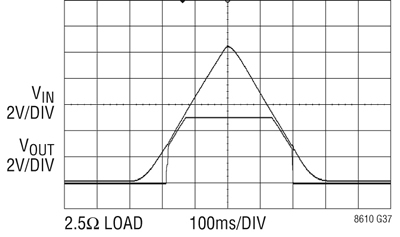
The LT8610s very low dropout performance is also very beneficial, particularly in applications which must regulate outputs through the use of stop-start or cold crank conditions. Figure 4 shows that even when the input voltage drops below the programmed output voltage, 5V in this case, the output is always 200mV (@1A) below the input voltage once the input exceeds 2.9V. This is important because such ECUs drives require one or multiple microprocessors/microcontrollers.
Although these are designed to operate from a nominal 5V, they continue to operate with supply voltages as low as 3V. So in a cold crank scenario, the input can drop as low as 3.2V and the microprocessor can continue to operate, enabling the ECU to operate seamlessly through cold crank.

Figure 4. LT8610 Dropout Performance
Furthermore, the LT8610’s fast minimum on-time of only 50ns enables 2MHz constant frequency operation from a 16V input to a 1.8V output, optimising efficiency while avoiding critical noise sensitive frequency bands such as AM radio.
Conclusion
The rapid growth of very complex electronic systems in automobiles has created even higher performance demands on power management ICs. Depending on where the power supply operates on the automotive power bus, they may be subjected to stop/start, cold crank and load dump conditions and must be capable of accurately regulating an output voltage throughout these conditions.
Additionally, some of these systems will operate in an always on standby mode, requiring minimal supply current. As more electronic systems are added in ever shrinking spaces, minimising the solution footprint while maximising efficiency is also critical. Fortunately ICs that meet these demands are already available paving the way for even higher electronic content in future cars.


