A guide to DAS optimisation
The optimisation of an in-building distributed antenna system (DAS) can provide flexible network designs which right-size the solution to the requirement, while reducing costs. Moti Shalev, Director of Product Management at Axell Wireless, explores more in this ES Design magazine article.
In 2012, mobile video traffic represented more than 50% of all mobile data for the first time, while global mobile data traffic grew by 70%, reaching 885 Petabytes (PB) per month by the year end; up from 520 PB per month at the end of 2011. To give this figure a perspective, one PB is 1015 bytes; equivalent to 1,000 terabytes. These astounding trends are driving operators to address their networks with a particularly sharp focus on indoor coverage; it is now widely acknowledged that indoor use accounts for 80% of mobile data traffic and forecasts show that the pace of growth will certainly not abate over the next five years (Figure 1).
 per month of mobile data traffic by 2017.jpg)
Figure 1: Cisco Forecasts 11.2 Exabytes (1,000 Petabytes) per month of mobile data traffic by 2017
Requirements relate not just to the world of business; a stadium capable of holding 90,000 visitors, for example, can generate peak traffic equivalent to a city with 500,000 inhabitants. Of these two, the stadium would be by far the biggest coverage challenge since most of the visitors would be using their devices at the same time: an exceptionally high level of demand for network service in a concentrated timeframe.
The demands for robust network connections are further intensified by the communication needs of emergency services; the provision of such services being critical in all environments which can, through their very structure and often obstacle-intense characteristics, compromise signal propagation (obstacles range from man-made barriers to coverage, such as neighbouring buildings, to unavoidable location characteristics, such as being underground).
Flexibility
The flexibility of the distributed antenna system (DAS) and its ability to break-down the coverage challenge into sectors provides both coverage and capacity solutions; seamlessly channelling mobile operators’ networks into buildings and other inherently difficult locations. Over a fibre optic cabling infrastructure the DAS brings the signal inside the building and caters for every major wireless technology including GSM, WCDMA, and LTE. At its simplest, a DAS addresses effective signal propagation by making the big challenge of indoor coverage no more daunting than a series of small challenges. Addressing each one specifically within its ‘sector’ passes the challenges up the line in progressive stages, from localised (remote) optical units (repeaters) through to head-ends (the optical master units which convert signals from RF to light in a fibre-fed repeater system) through to the base station (the base transceiver station, referred to as BTS). The BTS can be inside the building, or at a base station ‘hotel’, or externally located up to several kilometres away. Another option is to feed the DAS through an off-air digital repeater.
The system now also extends to provide IP backhaul infrastructure for other devices needing IP backhaul support, including, for example, small cells or devices such as the surveillance cameras installed in many public venues.
Possibly as recently as eighteen months ago, operators were not optimising their indoor systems for next generation technologies, typified at the time by the arrival of 3G. Technology has moved fast, as the statistics quoted have highlighted. Those same operators are now engaged in renewed capital expenditure as they go back to underserved locations to add base stations, or replace entire systems, in order to reduce noise levels in line with the requirements of new technologies. Today, such situations can be avoided and nobody can be blamed for not having anticipated the pace at which the demands of the mobile world would change.
It’s a lesson from which the industry as a whole has learned; a flexible system enables operators to augment indoor coverage and capacity as required.

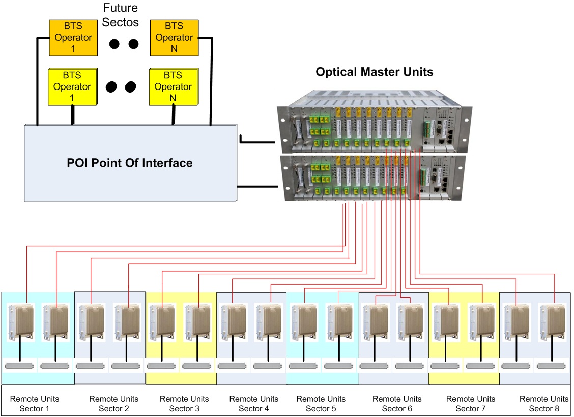
Figure 2: DAS architecture
The design stage has become more critical than ever before as operators now give high priority to future-proofing their indoor coverage systems. Delivering the highest achievable performance depends on maximising the desired factors; a relatively straightforward affair arising from rigorous RF design procedures. High performance depends also on minimising the undesired factors; interference, or ‘noise’ comes at the very top of the agenda in this regard. Production of a robust architecture plan is now a well-established discipline — interactive apps are available that drive a comprehensive check-list approach to the process. This is the stage at which decisions need to be made regarding the relative power of the remote optical units, dictated by the requisite coverage sector, which then informs decisions on the number of units required together with the number of optical master units, which then propagate the signal from the remote and take it on to the BTS (Figure 2).
Mix & Match
Xhead: Mix & Match The selection of high power or low power remotes is decided at the design stage of any multi-band fibre optic system when the layout of the infrastructure is first specified, reflecting coverage requirements. A low power remote typically has a composite output power of 20dBm at the antenna port, compared to up to 37 to 43dBm for a high power remote. Given arguments for and against both types of remote, the optimal solution often involves deployment of both.
In the case of a high-rise building, for example, the use of low power remotes would typically involve at least one per floor; a configuration which necessitates the installation of more optical master units (OMUs) also known as head-ends, as well as the laying of more cable. In short, more effort and more costs are involved. From the points of view of an effective network, an optimised architecture and cost control, the higher powered remote is at the very least adequate for the requirement. It is capable of coping with present and future needs within a fixed space scenario, where demand can be confidently forecast (governed by floor size and therefore maximum occupant capacity).
The use of high power remotes facilitates a DAS architecture in which five, six or even seven floors, in the case of a high-rise building, can be covered from one unit. This approach can often be governed by cabling restrictions and access permitted to the systems integrator at the installation stage; factors which have to be accommodated for during the design process. The implication of such restrictions, in the absence of any acceptable workaround (acceptable to all parties including facilities management, building owners and network systems integrator) could be that low power remotes are specified as logistically appropriate even if they are not the optimal solution. Though, technically-speaking, this may be viewed as a compromise, such a solution exemplifies the flexibility of the DAS; wherever wireless coverage is needed, a distributed antenna system can be designed to deliver it. It is important to be mindful of the flexibility of DAS in this regard, as a real world solution it can be configured in response to real world restraints whilst still delivering on its network promise of best-in-class coverage solutions. Additional sectors can be added as required, especially in large venues such as sports stadia, convention centres and airports.
Whatever the configuration, the key consideration is to ensure that the base station itself is not affected by high noise. DAS installations feed base stations, so if they have a high noise figure it can interfere, or cause capacity issues, with the base station. The converse is true; the lowest possible noise figure ensures maximum data throughput.
It follows, then, that the lower the noise figure on a remote the lower the overall noise figure for the system as a whole. Best-in-class noise figure on a high power remote is as low as 3dB typical (maximum gain) and on a low power remote 10dB typical (maximum gain). Indeed, at this point in time it appears that 3dB is the lowest noise figure in the industry, equivalent to the noise figure at the base station.
To measure noise levels, the calculation for an example system of 10 remotes would be 10 log (No. of remotes) + noise figure of a single remote. Taking the figure of 3dB, the formula to assess noise levels is therefore 10 log 10(10)+3 = 13dB. This is currently the lowest overall achievable noise figure; it is not uncommon for systems to show noise figures in the region of 20dB.
Capacity
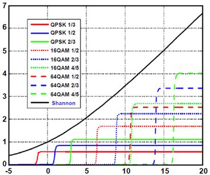
The Shannon-Hartley Channel Capacity Formula is a widely used methodology for assessing capacity optimisation by measuring the relationship between throughput and noise. The formula reads: C=B log 2(1+S/N), where:
- C = Capacity bits/s/Hz
- B = Bandwidth
- S/N = Signal to Noise ratio. This is related to the S/N ~ 1/R n , n= path loss exponent
- S/N ~ 1/NF
With no change in such variables as power, bandwidth, and frequency, the operator needs to come closer to the BTS for higher data rates and maintain the noise figure as low as possible as previously discussed. Figure 3 shows, on the basis of this formula, how higher signal to noise ratio (S/N) is required to achieve maximum capacity in higher order modulation (HOM) schemes such as QPSK and QAM.

Figure 3: Shannon-Hartley Channel Capacity Formula
Having addressed coverage and capacity at the design stage, progressing towards installation, operators can future-proof the DAS system to be ready for capacity growth simply by adding more sectors, without the need to revisit the infrastructure. Flexibility in the fibre optic head-end unit can allow support for up to eight sectors from a single head-end (a single chassis) — if an installation starts with two sectors, for example, capacity can be doubled twice without the need to change the infrastructure, add more head-end or remote units, or fibre optic or coaxial cables.
One fully integrated solution enables the same cables to be used from the remotes to the head-end/s. Changes can be effected in the point of interface. ‘Carrier-grade’ IP backhaul for small cells or Wi-Fi access points can be fed off the DAS. This feature reduces both CAPEX and OPEX since there is no need for the operator to deal with multiple vendors for different systems, there is no requirement for the complex cabling that would result from such an approach, and no need for the increased costs of running separate systems in one location. In terms of the efficiency of the network, there will also be less RF interference.
Running separate infrastructure for the DAS and each set of IP devices increases the installation time and cost and can also cause potential interference between the systems. Operators can now utilise a single infrastructure over a single fibre optic cable, supporting both the DAS remote units and the IP backhaul applications. The favourable cost implications are self-evident but it is perhaps more in the innate scalability and liberating flexibility of the DAS that the true long-term benefits reside. Scalability is innate due to the design approach of ‘sectorisation’ whereby remotes can be added as capacity and coverage is required. Flexibility is ‘liberating’ because operators are no more constrained by fixed and rigid structures that require major re-investment as wireless communications technology rolls forward which, as the forecasts show, will continue to be the defining characteristic of the mobile world for some years yet to come.
Key to DAS optimisation is the requirement to take real world considerations into account when designing the infrastructure, establish architecture which permits growth through the inclusion of additional repeaters as and when required, and ensure high quality through the lowest attainable noise figure, which means deploying the highest quality equipment: three simple steps towards one clearly logical solution.
DAS in a nutshell: Signals are coupled off from a nearby base station or off-air repeater to the OMU and then distributed via fibre to one or several remote units. A single fibre optic cable connects the remote units to the OMU. Different colours (wavelengths) are used in order to combine the uplink of different remote units in a cost effective way.
Author profile: Moti Shalev is the Director of Product Management at Axell Wireless, joining in 2009 as Product Marketing Manager. He graduated in 1993 with a B.S.C EE in Electrical Engineering after completing his army service in the I.D.F as a practical engineer in development, maintenance and operation of special commint systems.


