
Power line comms in smart energy grid infrastructure
Transformers in particular have advanced as key components that help developers meet the narrowband design requirements in a rapidly increasing line of telecommunication systems that are part of next-generation energy grids. Designing galvanic isolation for a line coupling circuit can meet narrowband requirements in the latest power line communication (PLC) -based systems.
This article originally appeared in the Jan'23 magazine issue of Electronic Specifier Design – see ES's Magazine Archives for more featured publications.
Infrastructure
Power grids have traditionally consisted of centralised power whereas older systems relied on generated fossil fuel power that was transferred to the customer through large networks of different power lines. As more renewable energy sources are added, the grid has transformed into one where power is delivered from local sources. The addition of more renewables challenges grid operations. Wind and solar are intermittent, so their power output can change rapidly which sets up a potentially unbalanced grid condition because power generation must equal demand. An imbalance for too long could lead to a blackout situation, which has led to advances in developing a more intelligent and robust ‘smart grid’ system. One advantage of the smart grid is that it can detect a localised power outage rapidly by using communication technologies such as PLC.
The need for comms
Energy systems demand reliable, effective, and low-cost communication technologies that can transfer vast amounts of data smoothly. PLC technology uses existing power line infrastructure to seamlessly transfer information. It has also been proven for transferring large amounts of data when employed in smart energy infrastructure designs. An advantage for grid operators is that PLC technology eliminates bandwidth variations as equipment does not have to share the communication channel with other systems.
Smart grid communication is accomplished by either wireless or wired methods. Wired communication offers data security, cost-effectiveness and extensive coverage in addition to available infrastructure from the use of existing power lines. Wired PLC technology does not have bandwidth variation issues and PLC signals do not get obstructed by mountains or tall buildings. The main challenges for PLC technology are related to signal attenuation and noise. These can be overcome with a careful design that helps to minimise the disturbance these issues can cause.
On the other hand, wireless can be installed rapidly but issues with cost, security, coverage area and latency have led to a reluctance to deploy in smart grid applications.
Extreme conditions
Power systems operate at very low frequencies and very high power, while communication systems operate at high frequencies and low power. PLC circuits must be designed to handle these extremes; a key part of the PLC circuit is the line coupling circuit. This has two primary functions - isolation and coupling. Isolation is required to block mains high voltage from the low voltage modem circuit, while also providing a path for the communication signal to pass via the AC mains line.
For a coupling operation to the mains, a high pass filter is necessary to filter out mains voltage and its associated harmonics using a high-voltage capacitor placed before the transformer. A transformer provides galvanic isolation between its primary and secondary sides. The high voltage capacitor, in conjunction with the leakage inductance of the coupling transformer, creates a series resonant coupling circuit. This series resonant circuit forms a second-order band pass filter.
Bourns developed its transformers for Narrowband PLC (NB-PLC) technology to facilitate separating the AC mains signal and PLC signal. The PFB series is qualified with the ST Microelectronics ST8500 programmable PLC modem SoC and the STD1 line driver. As a result, it is suitable for both long-distance rural and urban applications.
In addition, designs must typically comply with the European CENELEC EN50065-1 standard, which defines maximum signal levels as well as permissible carrier frequency bands. It is also important to match the modem impedance with the power line impedance. Often, it is not possible to change modem impedance so designers can use a transformer’s impedance-matching characteristic. The impedance of a transformer is determined by its turn ratio. When this figure is known, it is possible to match the modem impedance and the power line impedance.
Transformer deployment
Transformers that support PLC technology provide the communication galvanic isolation necessary to provide reliable, real-time measurements and efficient system control. They are also able to support both indoor and outdoor communication, in the low and medium voltage range. Deployment is cost-effective, as the communication medium is done over existing power lines minimising the need for additional infrastructure.

Featured products

MAX17793
Analog Devices Inc.
3V to 80V, 3A, High-Efficiency, Synchronous Step-Down DC-DC Converter
| SKU: | MAX17793 |
|---|---|
| Stock: | 9316 |
| Cost: | $3.64 |
MAX22516
Analog Devices Inc.
IO-Link Data Link Controller with Transceiver and Integrated DC-DC
| SKU: | MAX22516 |
|---|---|
| Stock: | 8000 |
| Cost: | $5.42 |
Product Spotlight
102991834
BeagleBoard

Single Board Computer (SBC), BeagleY-AI
AM67A BeagleY-AI Jacinto 7 AR...
| SKU: | 2820-102991834-ND |
|---|---|
| Stock: | 271 |
| Cost: | $55.61 |
SC1110
Raspberry Pi
Raspberry Pi 5 2GB
The Raspberry Pi 5 2GB model represents a leap for...
| SKU: | 2648-SC1110-ND |
|---|---|
| Stock: | 116 |
| Cost: | $38.33 |
AKX00069
Arduino
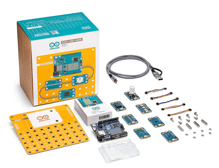
Arduino Plug and Make Kit
The Arduino Plug and Make Kit features the ...
| SKU: | 1050-AKX00069-ND |
|---|---|
| Stock: | 980 |
| Cost: | $66.97 |
300361-0011
Molex
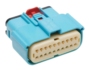
MX150 Mid-Voltage MatSealed Female Connector Assembly, Dual Row, 20 Circ...
| SKU: | 900-3003610011-ND |
|---|---|
| Stock: | 280 |
| Cost: | $2.37 |