Input protection for switched mode inverters and converters
These days, a typical specification for a power converter starts with a list of international standards that must be met for EMC and safety compliance. The requirements for functional performance are often many pages into the document.
EMC includes limitation of conducted and radiated emissions, immunity to transients and surges on the power lines and immunity to levels of external electromagnetic radiation and electrostatic discharge.
The relevant safety and EMC standards depend on the application but UL/EN 60950-1 for safety in IT systems and the European EMC directive standards in the EN 61000 series are commonly used. Standards change or are replaced regularly so the designer must ensure that the latest is used. EN 60950-1 for example will soon be replaced by EN 62368-1. Specific applications such as medical and test equipment have their own standards.
Safety requirements are linked with EMC because a result of an EMC-induced failure could be a damaged component which then presents a shock or other hazard to personnel. Also, safety standards require designers to ensure that a single failure of a component or connection leaves the equipment safe. A comprehensive input filter has to take all this into account without degrading the electrical performance of the converter.
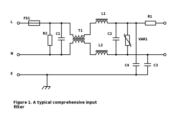
It’s possible to consider all the requirements of an input filter in isolation and assemble components to achieve the required performance. A filter which might do this is shown in Figure 1. C1 and C2 along with L1 and L2 reduce differential mode (DM) noise, T1 along with C3 and C4 reduce common mode (CM) noise, R1 provides inrush current suppression and VAR1 provides attenuation of transients and surges. FS1 protects wiring in case of short circuits downstream and R2 discharges C1 and C2 at power-down. It’s useful to remember that although the EMC standards do not put a limit on DM noise, it is always best to minimise it as it can convert into common mode, and in fact the standard test method for measuring CM noise using a LISN to CISPR-22 will always indicate half of the value of the DM noise even if no CM noise is present.

A high power converter or inverter is likely to feature all of these components but open up a modern mobile phone adapter and you will see very little obvious input filtering. This illustrates the fact that meeting the standards depends heavily on the converter design and particularly the power level. It’s most important to design the power converter for minimum EMI from the start by using soft switching technologies and with very careful layout to keep any EMI currents circulating within the converter and not through external connections. For example, a main source of CM noise is through the capacitance of a switching semiconductor tab to a grounded heatsink so select a device whose tab is not a switching node or avoid grounding the heatsink. If the heatsink must be grounded then an electrostatic screen between the device tab and heatsink is effective. The screen should be connected to the converter DC-link voltage, suitably isolated. An ungrounded heatsink also has the benefit of reducing input mains leakage current - an example of how safety and EMC interact.
At low power, economies can be achieved. For example, if the common mode choke T1 is deliberately wound with some leakage inductance, L1 and L2 could possibly be omitted; FS1 and R1 could be replaced by a single fusible resistor; C2 may be unnecessary depending on the level of EMI experienced and VAR1 may be unnecessary depending on the application environment and circuit impedances. Often low power applications are ‘Class II’ or earth free. In this case C3 and C4 would not be fitted but similar capacitors would often be connected in series from input to converter output.
Let’s look at each component in turn in Figure 1, assuming all components are needed:
FS1 must be ‘fast blow’ and agency-rated at the operating voltage and maximum running current with some margin. However, the fuse has to guarantee to open with short circuits downstream which might otherwise cause a shock or fire hazard. Creepage and clearance distances in the converter primary circuit are often reduced on the condition that the fuse opens with particular short circuits. Note that DC input converters require different types of fuses that self-extinguish after opening, typically sand-filled.
VAR1 must be rated for the highest line voltage and to absorb energy from the specified line transients without damage. Its energy rating does depend on other circuit impedances which could usefully limit current.
R2 discharges C1 and C2 to a safe voltage on power-down within a time specified by the relevant standard. It must be rated for the highest input voltage and it should withstand transients on the input without failure. A conflict exits in that the resistor has to be low enough in value to discharge the capacitors quickly but not so small that the nominal dissipation in the component exceeds the target light or no-load dissipation for the converter. A solution is the ‘CAPZero’ product from Power Integrations which discharges capacitors then actively disconnects itself. Note that if the value of C1 and C2 together is less than 100 nF, R2 can be omitted.
C1 and C2 ‘X’ capacitors attenuate converter DM emissions along with L1 and L2 and help to absorb transients from the input supply. These are usually large components as high capacitance is often needed and they have to be rated not only at the continuous input voltage but also for over-voltages on the line. The ‘overvoltage category’ of the application according to the relevant safety standard sets the over-voltage level requiring either ‘X1’ type rated at 4 kV test or ‘X2’ type rated at 2.5 kV test.
C3 and C4 ‘Y’ capacitors reduce CM noise externally by providing a low-impedance path for the noise to circulate inside the converter. The capacitors have to withstand line to earth voltages and transients so again, according to ‘overvoltage category’, are either ‘Y1’ type rated at 8 kV test or ‘Y2’ type at 5 kV test. There are strict limits to the allowed capacitance values however as under the fault condition of an open earth connection, current from the line can pass through the ‘Y’ capacitors to a chassis connection and to a user. The maximum current allowed is set by the standard and installation but can be as low as 10 µA in the most sensitive medical applications.
T1 is a ‘common mode’ or ‘current compensated’ choke providing attenuation for CM noise. Each winding is phased such that the normal running current magnetic field cancels in the core so high inductance windings can be used without fear of core saturation. Common mode noise current does not cause cancelling magnetic fields so a high impedance is ‘seen’ by the current. T1 is often toroidal construction with appropriate separation between the windings for the line to neutral voltage.
L1 and L2 are simple chokes providing attenuation for differential mode noise. These chokes see the full running current with no field cancellation so have to be rated to avoid saturation. This limits inductance value and core type, iron powder material being a common low cost solution.
R1 limits inrush current to following capacitors to avoid stress and ‘nuisance’ opening of FS1. However, at higher powers the normal running dissipation in R1 can be high so it is often replaced with a negative temperature coefficient (NTC) thermistor or a circuit which shorts the resistor after start-up by a TRIAC or relay. R1 should be a type with high surge current rating, typically wire-wound.
TDK manufactures many products suitable for the elements of filter networks including the series S, E2/E3(K1) and Q for varistors, S364x and S464x for thermistors, B3292x for X2 capacitors and B3202x for Y2 capacitors. Their B8245/6/7/8 series of common mode chokes covers a wide range of applications while their extensive range of ferrite cores can be used for custom solutions. Complete filter modules are also available in for example their B84143 series.
Click here for more information.


