Data centres changing power-conversion tactics to save energy
Internet applications and services are executed in large data centres comprising hundreds to thousands of individual servers. These data centres represent a new class of large-scale machines driven by complex and rapidly evolving workloads. Authors: Alessandro Zafarana, Max Picca, Osvaldo Zambetti, Pierluigi Gardella, STMicroelectronics.
Because of the concentration of powerful computing resources, power consumption is a critical factor in the total cost of ownership and maintenance of the data centre. Moreover, the gigantic scale of the application domain creates an extremely dynamic, heterogeneous load distribution across the servers’ clusters, increasing the uncertainty in the power consumption across the data centre and the variability among clusters.
As a result, even if a data centre uses a load balancing agent to dynamically adjust the load, performance would still vary since servers run multiple applications and the work they need to do is neither constant nor predictable.
In other words, a cluster of 20,000 servers could reach very high utilisation rates. Or that same cluster could have a low average utilisation with most of the time spent in the 10–50% CPU utilisation range. An evidence can be found where the average activity distribution of the load shared among 20,000 servers over a period of three months is reported.
In this environment, saving energy must be opportunistic and should be managed via hardware control to ideally consume almost no power when in active idle states, when the systems are still available to do work and gradually consume more power as the activity level increases.
Any power engineer worth his salt knows that any switching power converter has an optimum operating point where its efficiency is maximised. They also know the power losses of switching converters don’t increase linearly with the load. In a fixed-frequency forward converter, switching, driving, and joule-conduction would never show linear power loss versus output power characteristics. So the ideal target of a gradual increase in power losses that depends on the utilisation rate of a cluster of servers cannot violate the rules of physics.
The only engineering solution is to factorise output power so utilisation rates would refer to the different (efficiency-optimised) operating points of a power converter. Factorisation (see Figure 2a) implies parallelism among multiple power converters, each designed to be 'the most' efficient for that utilisation rate. The parallel power converters act as a special power engine where each converter delivers energy to the load synchronised perfectly to the utilisation rate of the cluster of servers. Turning the converters on or off in sequence when the load is changing is one of the biggest design challenges a power-system architect faces. Furthermore, a power engineer faced with all the multifaceted characteristics necessary for an efficient modern server processor: increased complexity, accurate reliability estimations, mean times between failures -as well as electric compliance issues and trade-offs between space, area occupied or simply density - versus the relationship of ‘ideal and gradual’ between power losses and utilisation rates—might well throw in the towel and give up on the solution as being too 'artistic.'
This challenge, in fact, is composed of different tasks. An active control system that verifies, monitors, and balances the power delivered among the factorised power converters would improve reliability. A dedicated control system that minimises the transient response by synchronising the power converters would increase the density of the power components and reduce the bill of materials. And the ability to use a load sensor to quickly turn on power converters to avoid disrupting computing tasks would improve electrical compliancy. A power system with all these features is called an 'energy proportional control system.'
The parallelism and power sharing among power converters is an 'ever-green' theme, and there are, already, several IC and power systems for this. None of these, however, can directly control the hundreds of amps required in the data centre with the mV of voltage tolerance for the highest-performance digital computing units.
In processor Voltage Regulation Modules (VRMs), the ability to control and balance the loads are implemented in a power architecture using a non-isolated 12V input bus. The buck multiphase converter, with Pulse Width Modulation (PWM) signals interleaved among the phases, is a de-facto industry standard since it reduces input and output current ripple and accelerates transient response. Many semiconductor manufacturers have products in the market implementing analogue or digital controlled systems in PWM fixed frequency. When the load current falls, it becomes unnecessary to continuously modulate all phases because the load current can be shared among the reduced number of cells. Phase shedding-disconnecting some phases at light load to improve converter efficiency-is equivalent to the turn-on and -off of the converters discussed earlier. Choosing the correct number of phases for each output current optimises the system efficiency, as demonstrated in Figure 2a. Finally, when the processor is idle, an efficient light load condition is required to maintain the conversion system efficiency in this working condition. This phase modulation, balance, and control meet the high dynamic requirements of high-performance microprocessors that require a low-voltage, high-current power supply with a fast transient response.
When the light load expires and a processor changes its p-state, this instantaneous wake-up of the phases can require as much as 230A at 800A/µsec, canceling any attempt to monitor the load because of the latency monitoring would cause.
At STMicroelectronics, we have adopted a control method based on constant on-time controllers (STVCOT), rather than PWM fixed frequency. In a fixed frequency controller, each phase duty cycle is determined by closing the total voltage loop and the current balancing loop that compares the phase current with the average phase current. In contrast, in the STVCOT the switching period of each phase is determined by the total voltage loop, while the On time is chosen to equalise the phase currents and adjust the mean frequency to a desired switching rate under steady-state conditions. We demonstrated the power factorisation and the energy proportional performance for the 12V multiphase converter: the patented STVCOT control system uses the instantaneous switching frequency to determine the sudden increase of load so it can trigger the turn-on of all phases. This helps minimise the latency of the energy-proportional design without excessive cost for the control-voltage-error ADC, digital design, and current-monitoring ADC. Figure 2b shows a block diagram of this control system.
Figure 2. a) Power factorisation: efficiency curves, b) Digital architecture of the proposed controller
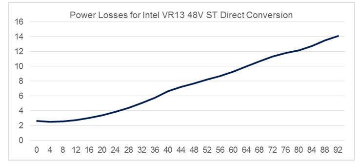
ST has extended this energy-proportional control system to a direct isolated resonant 48V conversion topology. The proportionality between output current and power losses can be derived from Figure 3.
Figure 3. Total power losses versus output current for ST 48V Isolated Direct Conversion, Intel VR13 Skylake CPU
This topology and the patented control technique guarantee high efficiency, even with the volatile and unpredictable utilisation rate in a data centre environment. Moreover, faster processors require fast adjustments during sudden changes of the load, and the system must assure energy proportional control will have negligible latency during those transitions. The latency between the sudden increase of the processor load and controller action could dramatically affect the transient system performance if the energy proportional design is infeasible and noncompliant to the load requirements. Electrical compliance of the digital load must be assured a priori.
These new isolated direct resonant 48V converters described are compliant to the power distribution architecture as presented by Google to the Open Compute Conference.
The application of the energy proportional control to the isolated direct resonant 48V converters is possible because
- They achieve excellent performance during the transients because the constant resonant time mimics what is already implemented in the 12V traditional multiphase Constant On-Time controllers.
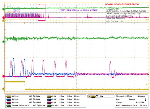
- They deliver better management in light load operation mode. See Figure 4 where light load transition occurs, shedding the converter switching frequency.
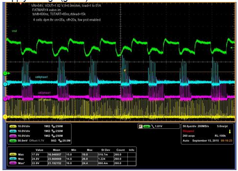
- They offer straightforward implementation of a fast resonant converter shedding technique. See Figure 5 where load and phase shedding occur.
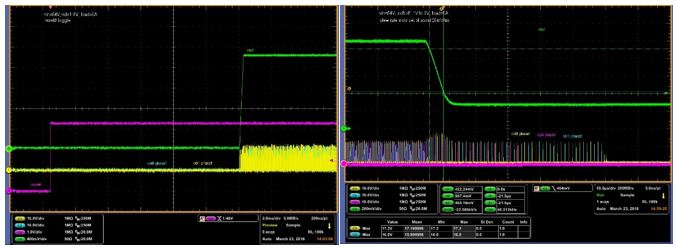
- With turn-on and turn-off of an Intel Server Processor in 20us, these converters support Power-Naps, to allow data centre software agents to opportunistically tune server workloads by increasing the workload on some server-board clusters and reducing the workload on others to zero. See Figure 6 where fast turn on/off of the converter occurs.

Figure 4. Transition to very light load and switching frequency shedding without affecting the processor power supply voltage (green)
Figure 5. Severe load transients trigger instantaneous turn on/off of the paralleled converters (yellow converter 1, pink converter 2, blue converter 3) without affecting the processor power supply voltage (green)
Figure 6. Fast converters turn on/off (25us) to enable processor Power Nap; processor voltage in green moving up and down at 20mV/us
One way to successfully implement energy proportion in a digital VR IC is by using the STRG006 controller, which receives the benefit of the controller translation from load current and instantaneous switching frequency. This relation is common to the12V Digital STVCOT from ST. The instantaneous frequency control comes directly from a VCO (Voltage Controlled Oscillator). It is the control variable of the COT architecture and therefore overcomes the delay required by a dedicated frequency measurement. If the system is working with N phases, the output of the VCO has a signal with a frequency that is N times single phase FSW. During a load transient event, the VCO frequency increases. If an instantaneous frequency reaches (N+1) times FSW, the controller enables another phase, and it adjusts the number of enabled phases when digital current monitoring information is available.
An important feature of all the Constant-On-Time controllers (and the isolated resonant converter is included) is the capability to adapt the switching frequency in light load operations. The switching frequency depends on the output load current when Discontinuous Current Mode (DCM) occurs. This represents an extension of the energy proportional design if the voltage regulator has the capability to maintain the same low latency response featured in Continuous Current Mode (CCM). To be noted is that for a fixed switching-voltage regulator, independently of its analogue or digital implementation, the latency requirement moving from DCM to CCM and vice versa makes compliance with regulation specifications very tough. The digital implementation of the Constant On-time controller is the key to being able to guarantee minimised CCM-DCM transition latency.
By ideally and gradually adapting the power losses to the utilisation rate, the new 48V isolated direct resonant converters from ST will contribute to making data centres that adopt the latest Intel Skylake Processors ‘greener.’ And the next time you are looking for an open restaurant at 2am or at peak times, you might want to keep that in mind.


