Voltage-fed or current-fed power topologies: a critical choice for users of multi-kW power sources
Many engineers working in a production, product testing or R&D role have a requirement for a high-voltage power source that is robust and capable of supplying loads of multiple kilowatts. Because of the nature of testing and R&D environments, this power source is often required to withstand abusive conditions.
By Bob Collins, Managing Director, Magna-Power Electronics (UK).
In the past, technology based on the Silicon-Controlled Rectifier (SCR) was the mainstay of high-power conversion. SCR technology lent itself to the development of simple home-grown power sources and could viably be produced in low volumes for specific customers by non-specialist engineering contactors. As long ago as the early 1990s, however, IGBT-based switching power supplies began to gain a foothold. Today, production, test and development engineers benefit from a wide choice of sophisticated switching power supplies with very high power ratings from manufacturers such as Magna-Power Electronics.
Earlier SCR-based power supplies contained bulky steel or iron laminated 50 or 60Hz transformers. The high-frequency operation of switching power supplies, by contrast, enables their magnetic components to be reduced in size and weight (by up to 80%). This allows for faster response times to line and load perturbations, makes it easier to filter output ripple and greatly improves the power factor.
Switch-mode supplies are, though, considerably more complicated than their SCR-based counterparts. Today, the case for developing a home-grown high-power DC switching source, or using a one-off design from a small system integrator, is weak, given that an off-the-shelf programmable power supply offers many advantages:
- Available immediately from stock;
- Proven high performance, offering accurate and stable outputs;
- User-friendly control and programming interfaces;
- Multiple remote connectivity options (such as RS232, GPIB, Ethernet, USB, RS485 and analogue);
- Fully tested and documented; and
- CE marked and compliant with all relevant safety and EMC standards, allaying the health and safety concerns involved in the use of home-grown solutions.
By buying in a high-power programmable DC source, the user benefits from a ready-made product and is free to concentrate on their core production, test or development function.
As stated above, however, the environment in which high-power sources are deployed often exposes them to abusive conditions. The principal disadvantage of switching power supplies is that the demands placed on the switching devices in high-power applications tend to make them less reliable than their SCR based counterparts.
Robustness, then, is a critical parameter to consider when choosing between different off-the-shelf power sources. This in turn requires users to consider the impact of a power source’s topology, and to compare conventional voltage-fed power supplies with the less common current-fed topology, since this choice has a big effect on the robustness and reliability of the product.
Characteristics of voltage-fed converters
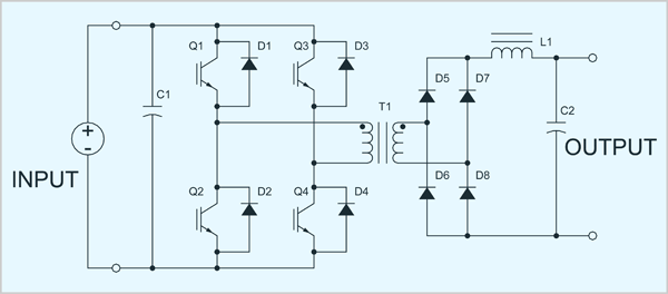
A simplified schematic of a voltage-fed converter is shown in Figure 1. The converter consists of an H-bridge (Q1 to Q4), power transformer T1, and output rectifier diodes D5 to D8. The input voltage source can be a battery, DC power supply or rectified AC bus. For practical reasons, capacitor C1 is required to ensure a low impedance bus at higher frequencies. Inductor L1 and capacitor C2 form a low-pass filter which removes the AC components on the output.

Figure 1 - Voltage-fed converter
With conventional hard-switched PWM modulation schemes, Q1, Q4 conduct for a fraction of a half-cycle and Q2, Q3 conduct for a fraction of the other half-cycle. This excites transformer T1 equally on alternate half-cycles. Averaging the rectified voltage on the secondary side of the transformer produces a DC output voltage that is proportional to the conduction period of the IGBT’s.
Timing on voltage-fed converters is critical. If IGBTs Q1, Q2 or Q3, Q4 conduct simultaneously, current rapidly rises in the conducting devices leading to failure in microseconds. To prevent this critical operating condition, designers introduce turn-on delays in the modulation schemes, monitor DC bus currents, and sense on-state conditions of the power devices. The challenge of successfully implementing these protective schemes is that the circuit must be both responsive to high-speed faults and insensitive to electrical noise. This is a formidable challenge, especially when power levels are in the order of tens of kilowatts.
Characteristics of current-fed converters
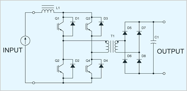
Current-fed converters are the electrical dual of voltage-fed converters. As shown in Figure 2, current-fed converters consist of an H-bridge, power transformer and output rectifier diodes. The input current source has to be created with additional power electronic circuitry. For practical reasons, inductor L1 is required to ensure a high impedance bus at higher frequencies. Unlike in a voltage-fed converter, the output filter consists of a single component, capacitor C1.

Figure 2 - Current-fed converter
In current-fed converters, voltage and current waveforms are transposed from that of voltage-fed converters. Operation requires IGBTs Q1 to Q4 to be PWM-modulated, but in this case, with the constraint that Q1, Q3 or Q2, Q4 are never allowed to be simultaneously placed in a non-conducting state. This constraint ensures the input impedance of the H-bridge is always finite; otherwise, a current source feeding into an open current would produce a destructive high voltage. Averaging the rectified current on the secondary side of the transformer produces a DC output current which is proportional to the conduction period of the IGBTs.
Transformer T1, being excited with a current PWM waveform, is insensitive to variations of on-state voltages, variations with rise and fall times, and erroneous switching states. With current-fed converters, core saturation can be prevented as long as the ampere-turn excitation is within the bounds of normal operation even if the current is DC.
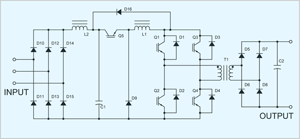
The disadvantage of current-fed converters is the fact that current sources are not commonly available and such sources must be created from a voltage source. Deployment of buck converters or choppers is an obvious choice because of their very efficient use of power semiconductors. With this extra power conversion stage, control can be placed in the current-fed converter, chopper, or both. Figure 3 shows a high-power converter with a 3-phase input rectifier, chopper, current-fed converter and output rectifier.

Figure 3 - Rectifier, chopper and current-fed converter
The novel feature of the current-fed converter combined with an input chopper is its performance under abnormal operating conditions. Transformer T1, IGBTs Q1 to Q5 and diodes D1 to D8 can all operate in a shorted state with system-level protection. Under such conditions, the rate of rise of current is a function of the applied voltage across inductor L1 divided by its inductance. Inductor L1 is typically sized to maintain a peak-to-peak ripple current within a fraction of its maximum value. As long as system shut-down occurs within the switching period of the chopper, peak currents are well controlled. Permitting an extended fault detection period allows fault protection circuitry to be well filtered, providing for robust, nuisance free tripping operation in environments subject to high electrical noise.
Magna-Power current-fed power sources
All Magna-Power power sources, available with output ratings from 1.5kW to more than 2MW, are based on current-fed power converters. The advantage of these power converters over their voltage-fed counterparts is that shoot-through and half-cycle symmetry cannot cause device failure or core saturation. In other words, the current-fed converters in Magna-Power power sources operate with the robustness of SCR based power supplies, but with the speed and responsiveness of a high-frequency switching power supply.
Current-fed power converter topologies are implemented less commonly than voltage-fed converters primarily because of cost and the more challenging packaging required. Ultimately, however, the protection provided by the current-fed topology will reduce long-term ownership and operating costs, and is best suited to the conditions encountered in typical production, testing and development environments.
For technical information about the programmable DC power supplies or to arrange for an in-depth demonstration, contact Magna-Power Electronics.


