TO thermal resistance and beyond
Heat dissipation is a key factor in the design of a power system; in a world where the trend is for more power in a smaller space, are TO-style packages still the best solution? TO packages were originally intended for discrete transistors, in fact TO stands for ‘transistor outline’. The metal flange that protrudes from the top, or the mounting hole in the packaging, makes them easily identifiable.
The flange’s role is to dissipate heat, but to make it more effective it can be connected to a metal plate that acts as a heat sink, usually made of steel or aluminium, or the flange can even bolted to the design’s metal plate housing. In order to decide if the TO package is the best solution for your design, it’s important to know the limit of the thermal properties the design will have to operate under.
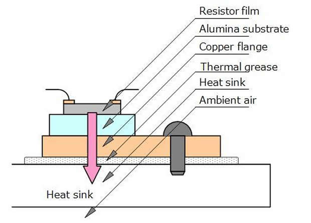
Thermal resistance is essential to understanding the thermal properties of a system. The thermal resistance is measured by calculating the sum of the thermal resistance parts, and in order to keep a system cool this has to be kept as low as possible. There are a number of factors that will affect the thermal resistance of a resistor; from the property of the component itself to the area of contact between the internal resistance film, the alumina substrate and the copper flange. Successful power resistors should be designed to maximise the contact area within their internal structure. An easy generalisation is that the bigger the actual resistor along with a higher rated power, the lower the thermal resistance. In order to maximise the effectiveness of the heat sink in terms of its thermal resistance, the size and shape need to be optimised, especially when not using a plate.

Cross-section of a TO-220 resistor mounted on a heat sink
The quality of contact between the flange and the heat sink is integral to the thermal resistance of a TO-packaged resistor. A smooth surface will provide the best contact, so usually a thin layer of thermal grease is added between the two parts. This is specially designed to have a low thermal resistance, typically around 0.005°C/W per square inch, which will have a negligible effect on the whole system’s thermal resistance. It’s important to note that different thermal gels and adhesives will have different effects depending on how thickly they need to be applied.
The maximum power that can be dissipated by the system can be worked out by calculating the maximum temperature difference between the heat source and the ambient air, and then dividing that by the total thermal resistance of the heat-flow path. In reality it is essential to build a prototype and verify the actual temperatures, as the ambient air temperature will change as the power components heat up when the equipment is active. There are other factors to consider as well when trying to maximise the cooling of a system; adding a fan to the design will have an influence on the air flow around the heat sink, as will the orientation of the heat sink itself and its location in regard to how close it sits to other hot spots in the system.
Understanding the thermal resistance in TO-package systems requires a detailed knowledge of the practical and theoretical factors summarised here. For a more detailed explanation of how thermal resistance affects your design download the resistors e-book.
By Phil Ebbert, VP Engineering at Riedon.


