Stretching the TO to its thermal limit
Riedon investigate the key factors that impact the thermal resistance for TO-packaged resistors and the factors that need to be understood to get the maximum from a TO package.
TO-style packages, commonly used for modern power resistors, were originally designed for discrete transistors (the TO actually stands for ‘transistor outline’). They are easily identified by the metal flange sticking out of the top, or sometimes they have a mounting hole directly through the packaging.
The flange is there to dissipate heat, and it can be used on its own, but more often than not it is bolted to a steel or aluminium plate heatsink, or the design’s metal plate housing. While TO packages were more than adequate when they were invented, today’s demands for more power in smaller and smaller spaces can stretch the thermal properties of these packages right to the limit. Understanding what that limit is and what it depends on is more relevant than ever as power designs continue to shrink.

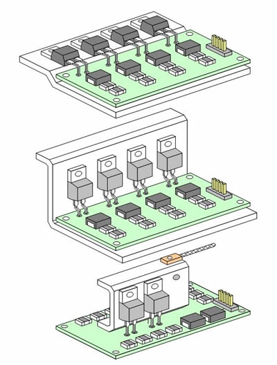
Above: examples of mounting TO-220 power resistors
When studying the thermal properties of any system, we of course need to consider its thermal resistance. For the purposes of cooling, low thermal resistance is good, high thermal resistance is bad, and the thermal resistance of a system is the sum of the thermal resistances of its parts.
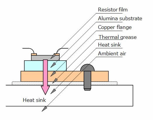
The resistor’s thermal resistance is dependent on the area of contact between the internal resistance film, alumina substrate and copper flange, and it’s a property of the component. Well designed power resistors will seek to maximise this contact area in their internal structure. In general, the bigger the physical size of a resistor and the higher its rated power, the lower its thermal resistance will be. Similarly for the heat sink, its thermal resistance depends on maximising its physical size (and optimising its shape, if not using plate).

Above: a cross-section of a TO-220 resistor mounted on a heat sink
The other key factor affecting thermal resistance for TO-packaged resistors is the quality of the contact between the flange and the heat sink. Since rough surfaces don’t make particularly good contact for thermal purposes, a specially designed material is often added between the two.
For TO packaged resistors it’s usually a thin layer of thermal grease, with a very low thermal resistance of around 0.005°C/W per square inch. This is low enough to have a negligible effect on the overall system thermal resistance, but note that other types of thermal gels or adhesives may have a bigger effect as they need to be applied in thicker layers.
We can easily calculate the maximum power that can be dissipated by the system as it is given by the maximum temperature difference between the heat source and the ambient air divided by the total thermal resistance of the system. For real life circuits though, building a prototype and checking all these temperatures is essential, since the heat dissipated by power components will naturally heat up the ambient air while the equipment is running. Other things that can affect the cooling of the proposed system include the air flow around the heat sink (particularly if adding a fan), the orientation of the heatsink and the proximity to other hot parts of the system. To get the absolute maximum from the TO package depends on a thorough understanding of all these practical factors as well as the theoretical ones.


