
How a noise-reduction pin improves system performance
In the article, 'LDO basics: power supply rejection ratio', Aaron Paxton discussed using a low-dropout regulator (LDO) to filter ripple voltage arising from switched-mode power supplies.
That isn’t the only consideration for achieving a clean DC power supply, however. Because LDOs are electronic devices, they generate a certain amount of noise of their own accord. Selecting a low-noise LDO and taking steps to reduce internal noise are integral to generating clean supply rails that won’t compromise system performance.
Identifying noise
The ideal LDO would generate a voltage rail with no AC elements. Unfortunately, LDOs generate their own noise like other electronic devices. Figure 1 shows how this noise manifests in the time domain.

Analysis in the time domain is difficult. Therefore, there are two main ways to examine noise: across frequency and as an integrated value.
You can use a spectrum analyser to identify the various AC elements at the output of the LDO. The application report, “How to Measure LDO Noise,” covers noise measurements extensively.
.png)
As you can see from the various curves, output noise, represented in microvolts per square root hertz (μV/√Hz), is concentrated at the lower end of the frequency spectrum. This noise mostly emanates from the internal reference voltage, but the error amplifier, field-effect transistor (FET) and resistor divider also contribute.
It’s helpful to look at output noise across frequency when determining the noise profile for a frequency range of interest. For example, audio application designers care about audible frequencies (20Hz to 20kHz) where power-supply noise might degrade sound quality.
Data sheets commonly provide a single, integrated noise value for apples-to-apples comparisons. Output noise is often integrated from 10Hz to 100kHz and is represented in microvolts root mean square (μVRMS). Some semiconductor manufacturers integrate noise from 100Hz to 100kHz or a custom frequency range. Integrating over a select frequency range can help mask unflattering noise properties, so it’s important to examine the noise curves in addition to the integrated value. Figure 2 shows integrated noise values that correspond with the various curves. Texas Instruments features a portfolio of LDOs whose integrated noise values measure as low as 0.47μVRMS.
Reducing noise
In addition to selecting an LDO with low-noise qualities, you can also employ a couple of techniques to ensure that your LDO has the lowest noise characteristics. These involve the use of noise-reduction and feed-forward capacitors, discussed in the article, “LDO basics: noise – how a feed-forward capacitor improves system performance.”
Noise-reduction capacitors
Many low-noise LDOs in the TI portfolio have a special pin designated as “NR/SS.” Figure 3 shows a common topology used to implement the noise-reduction feature.
.PNG)
The function of this pin is twofold. It’s used to filter noise emanating from the internal voltage reference and to either slow the slew rate during startup or enable the LDO.
Adding a capacitor at this pin (CNR/SS) forms a resistor-capacitor (RC) filter with internal resistance, helping shunt undesirable noise generated by the voltage reference. Since the voltage reference is the main contributor to noise, increasing the capacitance helps push the cutoff frequency of the low-pass filter to lower frequencies. Figure 4 shows the effect of this capacitor on output noise.

As Figure 4 shows, a greater value of CNR/SS yields better noise figures. At a certain point, increasing the capacitance will no longer reduce noise. The remaining noise emanates from the error amplifier, FET, etc.
Adding a capacitor also introduces an RC delay during startup, which causes the output voltage to ramp at a slower rate. This is advantageous when bulk capacitance is present at the output or load and you need to mitigate the inrush current.
Equation 1 expresses inrush current as:

In order to reduce inrush current, you must either lower the output capacitance or lower the slew rate. Fortunately, a CNR/SS helps achieve the latter, as Figure 5 shows for the TPS7A85.

As you can see, increasing CNR/SS values results in longer startup times, preventing inrush current from spiking and potentially triggering a current-limit event. Note that some LDOs with an NR pin do not implement a soft-start feature. They implement a quick-start circuit, which helps achieve minimal startup times even with large noise-reduction capacitors.
Summary
- Watch the 'LDO Basics' video series for trainings about LDO dropout voltage, current limit, power-supply rejection ratio, noise and thermals.
- Download the quick reference guide of popular LDOs and linear voltage regulators for a wide variety of applications, including industrial, personal electronics, communications equipment and automotive.


Featured products
MAX17793
Analog Devices Inc.
3V to 80V, 3A, High-Efficiency, Synchronous Step-Down DC-DC Converter
| SKU: | MAX17793 |
|---|---|
| Stock: | 9316 |
| Cost: | $3.64 |
MAX22516
Analog Devices Inc.
IO-Link Data Link Controller with Transceiver and Integrated DC-DC
| SKU: | MAX22516 |
|---|---|
| Stock: | 8000 |
| Cost: | $5.42 |
Product Spotlight
102991834
BeagleBoard

Single Board Computer (SBC), BeagleY-AI
AM67A BeagleY-AI Jacinto 7 AR...
| SKU: | 2820-102991834-ND |
|---|---|
| Stock: | 208 |
| Cost: | $56.24 |
SC1110
Raspberry Pi
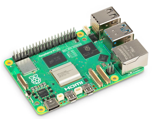
Raspberry Pi 5 2GB
The Raspberry Pi 5 2GB model represents a leap for...
| SKU: | 2648-SC1110-ND |
|---|---|
| Stock: | 0 |
| Cost: | $38.33 |
AKX00069
Arduino
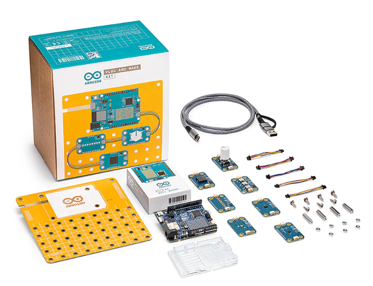
Arduino Plug and Make Kit
The Arduino Plug and Make Kit features the ...
| SKU: | |
|---|---|
| Stock: | 968 |
| Cost: | $66.97 |
300361-0011
Molex
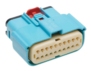
MX150 Mid-Voltage MatSealed Female Connector Assembly, Dual Row, 20 Circ...
| SKU: | |
|---|---|
| Stock: | 280 |
| Cost: | $2.51 |