
Understanding PCB schematic: The heart of electronics design
In the realm of electronics design, the term "PCB schematic" often comes up as a crucial element in the creation of printed circuit boards (PCBs). A PCB schematic is essentially a blueprint that outlines the electrical connections and components on a PCB. This article delves into the fundamentals of PCB schematics, their importance, and best practices for creating them.
What is a PCB Schematic?
A PCB schematic, or schematic diagram, is a detailed and symbolic representation of an electronic circuit. It includes components such as resistors, capacitors, transistors, and integrated circuits, interconnected by lines that represent electrical connections. The primary purpose of a PCB schematic is to provide a clear and accurate roadmap for the PCB layout process.
Importance of PCB Schematics
- Clarity and Precision: PCB schematics ensure that every component and connection is precisely defined, reducing the risk of errors during the PCB layout and manufacturing stages.
- Troubleshooting: They serve as a critical tool for diagnosing and fixing issues in the PCB. By referring to the schematic, engineers can trace connections and identify faulty components.
- Documentation: A well-documented schematic provides a comprehensive record of the design, which is essential for future modifications, maintenance, or replication of the PCB.
Creating a PCB Schematic: Best Practices
-
Component Selection and Placement: Start by selecting the right components for your circuit. Place them logically and group related components together. For example, place all power-related components in one section and signal-processing components in another.
-
Clear Labeling: Ensure every component is clearly labeled with its reference designator (e.g., R1 for resistor 1, C1 for capacitor 1). This helps in easily identifying components during the PCB layout and troubleshooting stages.
-
Logical Connections: Use straight lines for connections and avoid crossing lines wherever possible. Utilize junction dots to indicate where lines intersect and connect.
-
Hierarchical Design: For complex circuits, use a hierarchical design approach. Break down the circuit into smaller, manageable sub-circuits and create separate schematic sheets for each. This improves readability and simplifies troubleshooting.
-
Signal Integrity Considerations: Pay attention to high-frequency signals and their paths. Properly route signal lines to minimize interference and maintain signal integrity.
-
Annotation and Notes: Include annotations and notes to explain the function of critical components or sections of the schematic. This aids understanding and collaboration among design team members.
-
Review and Simulation: Before proceeding to the PCB layout, thoroughly review the schematic for errors or omissions. Use simulation tools to verify the functionality of the circuit design.
Tools for Creating PCB Schematics
Several software tools are available for creating PCB schematics, each offering unique features and capabilities. Some of the most popular tools include:
- EAGLE (Easily Applicable Graphical Layout Editor): Known for its user-friendly interface and extensive component libraries.
- Altium Designer: A powerful tool that integrates schematic capture, PCB layout, and simulation capabilities.
- KiCAD: An open-source software suite that provides robust features for schematic capture and PCB design.
- OrCAD: Offers advanced simulation features and is widely used in professional engineering environments.
A PCB schematic is the foundation of any successful PCB design. By following best practices and utilizing the right tools, you can create accurate and reliable schematics that simplify the PCB layout process and ensure the functionality of your electronic circuits. Whether you are a hobbyist or a professional engineer, mastering the art of PCB schematic design is essential for bringing your electronic projects to life.
Remember, a well-designed schematic not only aids in the creation of the PCB but also serves as a valuable resource for troubleshooting and future development. Keep learning, experimenting, and refining your skills to excel in the fascinating world of electronics design.
Product Spotlight
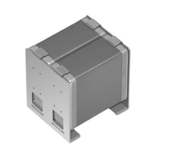
TBF10SL-4PS-B
ITT Interconnect Solutions

| SKU: | 1003-TBF10SL-4PS-B-ND |
|---|---|
| Stock: | 50 |
| Cost: | $45.59 |
CAA572C0G3A663J640LJ
TDK Corporation
| SKU: | |
|---|---|
| Stock: | 1037 |
| Cost: | $9.16 |
RA1113112R
E-Switch, Inc.
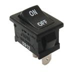
| SKU: | EG5619-ND |
|---|---|
| Stock: | 5586 |
| Cost: | $0.55 |
R30-3002002
Harwin

| SKU: | 952-1510-ND |
|---|---|
| Stock: | 6545 |
| Cost: | $0.76 |
NRF54L15-QFAA-R
Nordic Semiconductor
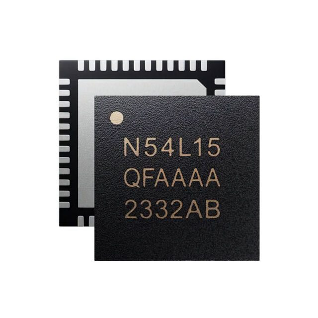
| SKU: | 4823-NRF54L15-QFAA-RTR-ND |
|---|---|
| Stock: | 0 |
| Cost: | $2.39 |
STDRIVEG611Q
STMicroelectronics
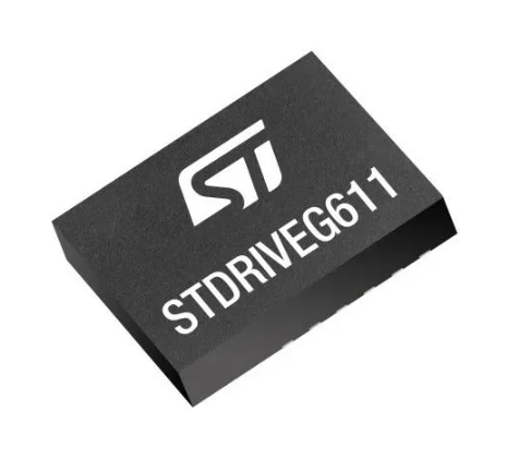
| SKU: | 497-STDRIVEG611QTR-ND |
|---|---|
| Stock: | 0 |
| Cost: | $2.63 |
TBF10SL-4PS-B
ITT Interconnect Solutions
| SKU: | 1003-TBF10SL-4PS-B-ND |
|---|---|
| Stock: | 50 |
| Cost: | $45.59 |
CAA572C0G3A663J640LJ
TDK Corporation
| SKU: | |
|---|---|
| Stock: | 1037 |
| Cost: | $9.16 |
RA1113112R
E-Switch, Inc.
| SKU: | EG5619-ND |
|---|---|
| Stock: | 5586 |
| Cost: | $0.55 |
R30-3002002
Harwin
| SKU: | 952-1510-ND |
|---|---|
| Stock: | 6545 |
| Cost: | $0.76 |
NRF54L15-QFAA-R
Nordic Semiconductor
| SKU: | 4823-NRF54L15-QFAA-RTR-ND |
|---|---|
| Stock: | 0 |
| Cost: | $2.39 |
STDRIVEG611Q
STMicroelectronics
| SKU: | 497-STDRIVEG611QTR-ND |
|---|---|
| Stock: | 0 |
| Cost: | $2.63 |