
One wire communication between two SLG46811
Many devices within the same design can communicate using different protocols (SPI, I2C, etc.). As is to be expected, most of these protocols require several dedicated lines for communication. However, there are many different applications in which the number of available wires is strictly limited and often times only one wire is available to send the data.
By Oleh Sapiha, Senior Applications Engineer, Dialog Semiconductor
The goal of this article is to highlight methods in which data can be effectively transmitted between two GreenPAK devices using only a single wire. In order to create the data transmission, two SLG46811 ICs will be used, connected by a communication line. Small size and great functionality combined with low current consumption and cost make the SLG46811 one of the most capable GreenPAK ICs for this kind of application, and can be easily applied for use in devices such as headphones, cellphones, wearables electronics, consumer electronics, handheld devices, and more.
How does the transmission work?
This section and any following sections contain the body of the document. Subsections can be added as required. Quick Parts are available for numbered equations, landscape pages, notices and tables.
The idea is based on using two separate ICs (two SLG46811), both featuring configured bidirectional PINs, and these two PINs are connected by one communication line (Figure 1).

Figure 1: Application circuit
In order to understand the principles of transmission, let's split the functionality into two parts. The first part is dedicated to the IC that transmits first, and the second part to the IC that receives first. The transmitter reacts at the Start event and pulls the line LOW for a certain time, which signals the receiver to prepare for a data stream.
Data is then sent at a frequency of 10kHz, where ‘0’ is coded as 25us pulse duration, and ‘1’ is coded as 75us pulse duration. Once the transmitter has sent 16 bits of data, the transmission direction changes and the IC that received the data starts sending data that, in this application, represents a voltage level code.

Figure 2: Application circuit
By default, the whole communication consists of 20bits (16bits transmitted and 4bits received), but it can be easily expanded to 32bits both directions.
Transmit first design realisation
The transmitter design (Figure 3) consists of 7 highlighted parts:
- Transmission start - When the rising edge is detected on the CLK input of DDF12, it sets to HIGH. This triggers DLY2 to begin counting. PIN12, which is connected to the data line, is pulled LOW when DLY2's time expired and passes through its signal. This indicates that the data transaction is ready to be started.
- Clock generator - The HIGH signal on the output of DLY2 is applied to CNT4/DLY4 which is configured as a rising edge One Shot (for more information on this, see GreenPAK Cookbook Technique: One Shot Implementation). The One Shot goes HIGH immediately, forces the OSC0 on, and remains HIGH until 16 clocks have been applied to its CLK input. CNT4/DLY4 determines the number of bits that will be sent to the receiver and, since the OSC0 frequency used is equal to 10kHz, the transmission will procced at a frequency of 10kHz.

Figure 3: Transmitter/Receiver design implementation
- Data generator - The clocks performed by OSC0 are passed through an inverter to Shift Register 0 (SHR 0) and Shift Register 1 (SHR 1) CLK inputs. The Shift Register is a new block in the GreenPAK, and functions as a configurable length serial-in serial-out (SISO) shift register with common CLK and RST pins. Unlike the PIPE DLY block found in some older GreenPAK ICs, the new Shift Register block is capable of storing an initial value for each of the shift register's individual DFFs, which can be useful when creating different pattern generators, state machines, frequency dividers, etc. This initial value data can be rewritten via I2C, but the shift register's D and CLK inputs should remain unchanged while the master is writing to the shift registers to avoid errors. In this application, the initial data in both SHRs are equal to 01010101b (0x55h).

Figure 4: Shift registers properties
In order to create the cycled data generator, the output of SHR 1 is connected to the D input of SHR 0. By clocking the shift registers, the output data will continuously be changing.
- 0/1 generator - Bits stored in SHRs are converting to the time-dependent pulses. ‘0’ is converted to a 25us pulse and ‘1’ is converted to a 75 us pulse. The converted bits duration is shown in Figure 5 (more details can be found in GreenPAK Cookbook Technique: Sending Serial Protocols Using Duty Cycle Detection).

Figure 5: 0/1 coding
- Bidirectional PIN - Setting the GPIO as a Digital input/output allows the pin's input/output status to be changed internally by the GreenPAK. Depending on the status of the PIN’s Output Enable signal, (OE, more details can be found in GreenPAK Cookbook Technique: OE PIN) the pin will be configured either as an input or output, which allows it to switch between sending and receiving a signal on-the-fly.
When in input mode, the pin is configured as a Digital Input without a Schmitt Trigger. When in output mode, the pin is configured as 1x Open-Drain NMOS. The initial output of 3-bit LUT1 and 3-bit LUT2 is a HIGH level, so PIN12 is initially set up as an output, which is pulled up to VDD by an internal 10kOhm resistor.
- Data decoding and storage - Once the 16 bits have been transmitted, CNT4/DLY4 goes LOW, which changes the 3-bit LUT2 input combination, thereby switching PIN12 to the input mode and allowing the switch from sender to receiver. The four data bits, which retain the same encoding structure as described earlier, will now be sent back to the original device by the second GreenPAK. The pulses pass through the 3-bit LUT11 to CNT3/DLY3, which is configured as a One Shot. This one shot generates a 50us predefined duration pulse. The falling edge of this One Shot signal then triggers the pin's current input status to be written to the Shift Register 1 (SHR 3). If the input pulse is shorter than the one-shot duration, the value ‘0’ will be clocked into the shift register. Conversely, if the input pulse is longer than the one-shot duration, a value of ‘1’ will be clocked into the shift register instead.
- Stop bit detection - Once the returning 4 bits have been stored, CNT1/DLY1, configured as a Delayed edge detector, generates a short glitch-like pulse, which resets the DFF12 and stops the transmission operation. In total, the IC has, at this point, sent 16bits and received 4bits of information. As soon as the rising edge is applied again, the DFF12 sets HIGH and the cycle will repeat.
Receive first design realisation
This design in Figure 6 shows how the receiver is implemented. The main parts of the design are located in the highlighted sections. Let’s go through each of them to explain out how it works.

Figure 6: Receiver/Transmitter design implementation
- - The data pin selected for this device is configured identically to the transmitter device, with the only difference being that this pin is set to input mode by default.
- - When the input PIN6 goes LOW, CNT1/DLY1 begins counting. Since it is a rising edge delay, DFF11 is set HIGH as soon as the delay time expires. This indicates that the receiver is ready to receive the 2 bytes of information from the transmitter.
- - After a successful start bit transmission, the 16 bits of data are presented on the data line, which are gated through AND (3-L8), to CNT0/DLY0. CNT0/DLY0 is configured as a one-shot, and is therefore responsible for determining the value of each bit before its falling edge clocks the newly acquired data into the shift register blocks. This data collection and storing methodology is identical to the scheme listed in the above transmitter design.

Figure 7: Shift register properties
- - The Start bit additionally triggers CNT5/DLY5 to begin counting the number of received bits. Upon detecting 12 received data bits, the clock generator based on MF2 (3-bit LUT10 and CNT2/DLY2) begins generating a periodic 50% duty cycle clock (more detailed in discussed in GreenPAK Cookbook Technique: Sending a Preset Number of Pulses) for the Extended Pattern Generator (EPG).
- - The EPG is a new block in the SLG46811. It has two inputs and eight parallel outputs. The two inputs are CLK and nRESET. At every rising edge of CLK input, a byte from NVM, which is determined beforehand using the EPG configuration window, appears at the outputs. nRESET is an active-low input which, upon receiving a low-level signal, replaces the data on the EPG's outputs with the defined EPG initial value. The EPG shares its outputs with I2C Virtual Inputs. The range of the Extended Pattern Generator is 92 bytes and is rated for a maximum allowable speed of 1MHz. The EPG can be used in a wide range of applications, for example, protocol generators (like SPI, I2C, UART), a 92-byte parallel pattern generator, power sequencers, state machines, various delay implementations, etc.
In this design, the EPG performs a conjunctive function, synchronising several parts of the design and creating the needed signals for the protocol transmission. It generates the clock for the voltage bit streaming and coding, changes the PIN’s OE for ‘1’ to ‘0’, and restarts the whole system after the receiving/transmission has completed. The properties of this design's EPG are shown in Figure 8.

Figure 8: EPG properties window
- - The Multi-Channel Sampling Analog Comparator (MS ACMP) is another new block in the SLG46811. The MS ACMP can make periodic samples of up to four channels, which subsequently latch at four outputs. It uses the internal OSC0 to switch between channels, change Vref, and output results. Initially, the IN+ signal of all four ACMP channels are connected to PIN8. However, the IN+ signal for each pin can be mapped to four separate PINs (PIN8, PIN9, PIN10, PIN11) to measure up to four independent voltages.
The timing diagrams in Figure 9 display how the voltage sampling and shifting is implemented.
Upon detection of the start bit, the MS ACMP starts measuring the voltage and latches the corresponding outputs. The goal is to store the voltage data and shift it serially. For this purpose, SHR3 is used. When a rising edge is detected by the CLK input of the shift register from an EPG signal (called Clock ‘Sa’) one of the ACMP channel outputs is clocked into the shift register.
A 4-bit multiplexer connected to all ACMP channel outputs is used to determine which ACMP channel output is sent to the shift register. SHR3 must be clocked four times to output the sampled voltage data. The ‘Sa’ signal keeps shifting the voltage data to the 0/1 generator.
- - After the voltage has been digitised and serially stored in SHR3, it is time to convert the signal into code, similar to the one which was applied to PIN6 at the beginning of receiving. The code transfers a ‘0’ and ‘1’ as 25us and 75us pulses respectively. EPG switches PIN6 to output mode and keeps shifting the voltage measured value through the SHR3 until all the data has been sent. The EPG then resets itself and deletes the start bit from DFF 11. The receiving/transiting is now stopped.

Figure 9: Voltage coding timing diagram
Results
Both designs were tested with hardware. Data coded in transmitter, and Voltage code, are shown and described below (it is considered that waveforms are taken from the SLG46811 which transmit first).
Table 1: Testing data

Channel 1 (yellow/top line) – PIN#2 (Start)
Channel 2 (light blue/2nd line) – PIN#12 (TX/RX)

Figure 10: Testing results

Figure 11: Testing results

Figure 12: Testing results
Conclusions
Dialog GreenPAK products are an ideal solution for the development of 1-wire communication protocol realisation. These ICs contain the large number of functional elements necessary for implementation of a variety of circuit design solutions. There are more than 50 ICs in the GreenPAK product family, in which each IC has its own special features and functions.
This, in turn, allows a significant reduction in the number of external circuit elements, and even allows for the creation of a system with highly specific requirements. Additionally, GreenPAK products feature the potential for very rapid design time and a very high level of configurability while showcasing low power consumption, small board area, and low cost.
The complete design file created in GreenPAK Designer software available for free can be found here.

Featured products
MAX17793
Analog Devices Inc.
3V to 80V, 3A, High-Efficiency, Synchronous Step-Down DC-DC Converter
| SKU: | MAX17793 |
|---|---|
| Stock: | 9316 |
| Cost: | $3.64 |
MAX22516
Analog Devices Inc.
IO-Link Data Link Controller with Transceiver and Integrated DC-DC
| SKU: | MAX22516 |
|---|---|
| Stock: | 8000 |
| Cost: | $5.42 |
Product Spotlight
102991834
BeagleBoard

Single Board Computer (SBC), BeagleY-AI
AM67A BeagleY-AI Jacinto 7 AR...
| SKU: | 2820-102991834-ND |
|---|---|
| Stock: | 270 |
| Cost: | $55.61 |
SC1110
Raspberry Pi
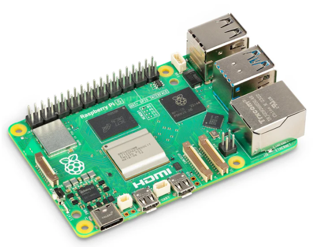
Raspberry Pi 5 2GB
The Raspberry Pi 5 2GB model represents a leap for...
| SKU: | 2648-SC1110-ND |
|---|---|
| Stock: | 101 |
| Cost: | $38.33 |
AKX00069
Arduino
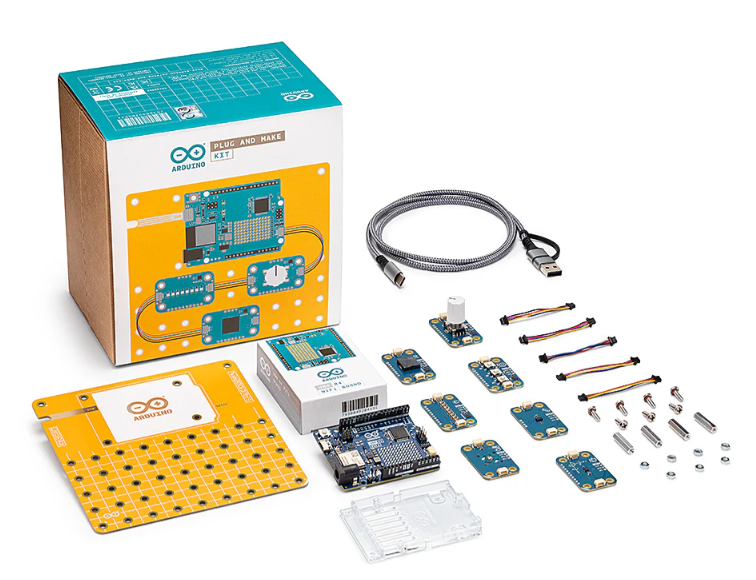
Arduino Plug and Make Kit
The Arduino Plug and Make Kit features the ...
| SKU: | 1050-AKX00069-ND |
|---|---|
| Stock: | 980 |
| Cost: | $66.97 |
300361-0011
Molex
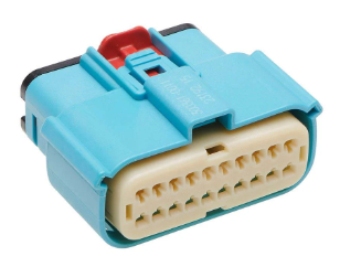
MX150 Mid-Voltage MatSealed Female Connector Assembly, Dual Row, 20 Circ...
| SKU: | |
|---|---|
| Stock: | 280 |
| Cost: | $2.37 |