TVS diode protection for VFDs/IGBT inverters
In virtually all industrial control systems, variable frequency drives (VFDs)/ inverters are commonly installed at the front end of motors in order to regulate speed and save energy. Based on differing input voltage requirements, inverters are often categorised as low voltage (110, 220 and 380V), medium voltage (690, 1140 and 2300V), or high voltage (3, 3.3, 6, 6.6 and 10kV).
Because VFDs/inverters are critical components in providing power, their operation, performance, and reliability are crucial to maintaining uninterrupted power. This application note focuses on TVS Diodes that can help ensure the reliability and operation of a VFD, even under adverse conditions.

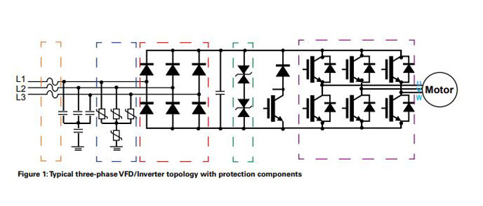
In Figure 1 above, the orange block highlights the AC line fuses for overcurrent or short circuit protection. For details on fuse selection, refer to the Littelfuse Fuse Selection Guide. The blue block identifies the transient suppressor used to protect against damage due to lightning-induced surges or harmonic voltage disruptions from the power line. Metal Oxide Varistors (MOVs) are widely used for this due to their clamping nature and high power capability. The MOV rating required will depend on the anticipated level of surge current and the AC line circuit topology involved. For example, if AC 380V power is connected as shown in Figure 1, in order to meet a 3kA, 8/20µs lightning surge requirement, three V20E250P (250V) UltraMOV high surge current radial leaded varistors can be used for line-to-line (differential mode) protection, and a single V20E550P (550V) UltraMOV High Surge Current Radial Leaded Varistor can be used for line-toground (common mode) protection.
The three MOVs are connected in a star configuration and separated with another MOV to the ground. This will provide line-to-line and line-to-ground protection. When choosing an MOV, the clamp voltage must also be considered. For this case, when two V20E250P Varistors are connected in series to provide differential protection, their resultant clamp voltage is about 1400V.
For a rectifier diode, capacitor and IGBT (Insulated Gate Bipolar Transistor), the voltage rating should be larger than this value so that it provides sufficient voltage protection for the overall system. At times, providing voltage protection for an overall system can be very difficult to accomplish, especially for high power line voltage applications of 600V or higher. For these cases, Littelfuse suggests an additional (or secondary) high power TVS Diode that offers accurate low voltage clamping capability to provide differential protection to the rectifier diodes, capacitor, and IGBT.

As shown in the pink block in Figure 2 above, two AK3-380C TVS Diodes can be added to provide differential protection during a maximum 3kA, 8/20µs surge current. The AK3-380 is a bidirectional, high power TVS Diode rated for 3kA (8/20µs) with a standoff voltage of 380V. The maximum clamping voltage of the two AK3-380C TVS Diodes is 1040V, which is much lower than that of MOVs.
As a result, they provide excellent surge protection to the 6-pack IGBTs while keeping the circuit within normal operating conditions. Adding these TVS Diodes offers designers greater flexibility in the selection of the rectifier diode and IGBT.
For a moment, let’s refer back to Figure 1. The red block highlights the AC/DC rectifier diodes. The green block identifies the brake-chopper circuit for DC bus overvoltage. (Consult the IGBT manufacturer’s application note for guidance on selecting the proper models of these devices.) The purple block shows the IGBT bridge DC/AC inverter for load powering. IGBT Protection: The IGBT provides both power transistor and power MOSFET benefits. It works at high frequencies and is easy to drive and to shut off; however, it also has a weakness. Normally, two portions need be protected to achieve a robust design:
- Because the gate is a MOS structure, it can be easily damaged by electrostatic discharge (ESD), an electrical fast transient (EFT), or an overvoltage induced by the Miller effect.
- In high power/high current applications, high voltage inrush may occur at IGBT terminal C and terminal E when the device is turning off.
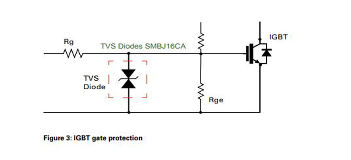
Because of the presence of the Miller capacitor (CGC), when driving the gate of the IGBT by pulse switching signal, it generates a high overvoltage that may damage the gate of the IGBT. To protect the gate during an overvoltage event, a bidirectional 600W TVS Diode is normally used, as shown in Figure 3. For example, in an application that normally needs a +15V bias to turn on the device and a -15V bias to shut it off, an SMBJ16CA TVS Diode would help to ensure the voltage remains lower than the maximum VGE of ±20V. The SMBJ16CA TVS diode has a VBR of about 17.8~19.7V, which is lower than the 20V maximum. In some cases, when the IGBT is driven by a unipolar driver, a unidirectional TVS SMBJ16A TVS Diode is used instead of the bidirectional one.
 Active clamping is a technique that keeps a transient overvoltage below the critical limits when the IGBT turns off. As shown in Figure 4, the standard approach for active clamping is to use TVS Diodes connected between the auxiliary collector and the gate of an IGBT. When the collector-emitter voltage exceeds the TVS Diode breakdown voltage, the TVS Diode starts to conduct and this current will add up to the value of the current of the IGBT driver output. This causes the gate-emitter voltage to increase. Thus, the IGBT is still held in an active mode and the turnoff process is prolonged. With the addition of the active clamping TVS Diodes, it will slow down the rate of change of the IGBT collector current, which results in a limited voltage overshoot or reduced IGBT turn-off overvoltage ΔVCE. Therefore, the TVS Diodes in series clamp this overshoot voltage. This is especially applicable to high voltage IGBTs, where the VCE exceeds 1200V.
Active clamping has been widely used for many years to limit the collector-emitter voltage of an IGBT during the turnoff event. As an IGBT’s collector-emitter voltage exceeds a pre-defined threshold value, the IGBT is partially turned on. The IGBT is then maintained in linear operation, thus reducing the fall rate of the collector current and, therefore, the collector-emitter overvoltage (see the solid line in Figure 5 with less slope IC, prolonged VGE, and a clamped value of VCE).
However, if there is no implementation of the TVS Diodes at the IGBT collector to gate during a turn-off event, the turnoff of the VGE will cause a sudden rise of voltage across the collector and gate to an even higher level, which will cause IGBT failure.


As Figure 5 illustrates, with active clamping circuit added, the VCE inrush voltage is reduced. But how can a designer calculate the number of TVS Diodes needed to provide such inrush protection? The following example may be useful for reference. As shown in Figure 6, the 1300V inrush voltage to the IGBT has a 0.5µs inrush time and a 0.5ms interval time.
Normally, the DC operating voltage is less than 600V for 1200V IGBT protection, so it would be acceptable to choose an 800V (VBR~900V) TVS Diode combination. Let’s also assume this 1300V inrush voltage will generate 5A of inrush current in the TVS Diode. (The level of current generated will also depend on RGE and R values.)
For this example, it is possible to use the SMCJ TVS Diode because it has a thermal impedance of RΘJA 75°C/W, so if this motor is working at an ambient maximum of 50°C, then the maximum allowed power for each SMCJ is (150- 50)/75=1.33W. The number of TVS Diodes needed would be determined by calculating 4.5/1.33=3.38pcs, so at least four TVS Diodes should be connected in series in order to have enough margin. Each TVS VBR should share 900/4=225V. As a result, four 1.5SMC220A TVS Diodes are suggested in this case. Note that the TVS series selection is also based on the actual value of the R and the RGE. In some cases, a lower rated TVS Diode, such as the SMAJ or SMBJ, might also applicable, depending on the actual working conditions.
Click here to find out more.


