
Take advantage of pre-layout simulation & simultaneous process design
As designs become more complex and time-to-market schedules become more demanding, engineers must take advantage of pre-layout simulation and simultaneous process design in order to beat the competition.
By Barry Olney, CEO, In-Circuit Design Pty Ltd.
Concurrent design can decrease product development time and also the time-to-market, leading to improved productivity and reduced costs. As a relatively new process strategy, initial implementation can be challenging but the potential competitive advantage means it is beneficial in the long term. Typically, a high-speed computer based product takes two to three iterations to develop a working prototype. However, these days the product life cycle is very short and therefore time-to-market is of the essence. A board iteration can be very costly, not only in engineering time, but also in the cost of delaying the product’s market launch. This missed opportunity could cost hundreds of thousands of dollars. All of the above impact on company profit, by increasing prototype costs and the time-to-market.
In a concurrent approach, pre-layout simulation can be done during design capture to establish the required design constraints. Functional sections of previously developed ‘golden’ boards can be reused giving high confidence in performance and multiple designers can be employed on the same layout. Post-layout simulation and mechanical integration can be done towards the end on the layout to ensure compliance to specification prior to fabrication. This process can dramatically reduce development time.
Process improvement is a systematic approach to ensure a development team optimises its underlying processes to achieve more efficient results. Process improvement is an aspect of organisational development in which a series of actions are taken to identify, analyse and improve existing design processes to meet new goals and objectives, such as increasing profits and performance, reducing costs and accelerating schedules. These actions often follow a specific methodology or strategy to increase the likelihood of successful results. There are many ways to improve efficiency in the PCB design process, such as: simulation; design reuse; collaborative PCB design; and virtual prototyping.

Figure 1 - A traditional design process compared to the simultaneous, or concurrent, design process
Simulation
Pre-layout analysis allows a designer to identify and eliminate signal integrity, crosstalk and EMI issues early in the design process. This is the most cost effective way to design a board with fewer iterations, rather than starting with the ‘find-and-fix’ based post-layout simulation. There are multiple facets to pre-layout analysis including: stackup planning for controlled impedance, SI, crosstalk, and cost control; dielectric material selection for manufacturing yield and high-frequency operation; PDN optimisation for product reliability and cost reduction; I/O buffer and drive strength selection; topology optimisation; termination strategy; floor planning for critical components; deriving layout routing constraints including trace width, spacing and length matching and signal integrity analysis to meet the design specifications with respect to noise margins, timing, skew, crosstalk and signal distortion.
Although the trace impedance is specified on the fabrication drawing, stackup planning is often left until Gerber’s are produced and the deliverables are sent off to the Fab shop. However, generally the virtual dielectric material selection and trace width and clearance provided do not match the desired controlled impedance. So, the CAM engineer returns the calculations that may require trace width and clearance changes; not what is needed at the end of the design cycle. This flawed process can be attributed to the fact that PCB designers do not have access to field solvers during layout and either have to wait until an SI engineer analyses the design or, as commonly occurs, wait for the fab shop’s report.
ICD has responded to this challenge by developing a bi-directional interface from the ICD Stackup Planner to Altium Designer 14. This new interface allows the designer to exact the rigid/flex stackup from the Altium Layer Stack Manager into the Stackup Planner. High-speed materials (up to 40GHz) can be merged from the Dielectrics Materials Library, of over 8,800 materials, and the impedance of multiple differential pairs can be simulated on the same substrate. Once finalised, the designer simply exports the data, including PTH and blind and buried microvia spans, trace width and clearances and differential pair rules back into Altium Designer. This allows the designer to route to impedance. A fabrication drawing of the stackup specifying all HDI requirements is also exported to Excel.

Figure 2 - Integration of the ICD Stackup Planner and Altium Designer 14
Similarly, PDN Analysis is often overlooked completely. It can’t be overstressed how important low AC impedance is for high-speed designs that demand high current drain at low core voltages. If the impedance is high at either the fundamental frequency, or any of the odd harmonics, then higher levels of electromagnetic radiation can be expected. This has a direct impact on product reliability and the ability to pass Electromagnet Compliancy.
For years, application notes have recommended the use of three decoupling capacitors per power pin. This generally consisted of a 100nF, a 10nF and a 47pF capacitor. The idea behind this was that different values provided current at different frequencies, but unfortunately not the right frequencies as all boards are different. As can be seen in Figure 3, multiple capacitors per decade are required to keep the effective impedance of the PDN below the target up to the required bandwidth. If too few capacitors are used, spread widely across the frequency domain, then there is a good chance that anti-resonance peaks in the PDN will exacerbate the problem.
Also, in this case, the use of 3M Embedded Capacitance Material (ECM) has been incorporated, which is the only practical way to pull the PDN low around the GHz region. This material provides 20nF/in2 which is an excellent way of amassing additional planar capacitance. The tight integration between the ICD Stackup Planner and PDN Planner allows the automatic transfer of the effects of different dielectric materials to the PDN for analysis.

Figure 3 - PDN Analysis using multiple capacitors per decade and 3M ECM planar material
Further efficiency gains
If the same switching regulator or processor and memory chips, for instance, are used on consecutive designs, creating a library of matching ‘reuse blocks or snippets’ for schematic and PCB makes the best use of existing design elements for future designs. Simply add a sub-circuit block to the schematic, transfer to the PCB database and load a predefined layout block including component placement, tracks, copper and text. Whether it is used for multiple channel designs, critical digital circuitry, RF circuit blocks or just to replicate a commonly used layout pattern, design reuse will save time and ensure repeatability of design: a proven, tested, working solution to just drop into place.
For many years designers have attempted team design, to avoid the seemingly unavoidable routing bottleneck, using multiple PCB designers to route different sections of the board at the same time.
Schematics and layouts can be divided into function blocks for example: power supply, analogue, digital, memory and SERDES. Or, multiple designers can work on the same section simultaneously in different parts of the world. I have done this many times, providing an over-night design service for US based companies. Co-design implies that a group of designers can work on a design at the same time and all their design inputs are accepted. But obviously, this is full of traps and there has to be some form of priority when merging databases.
In recent years some EDA companies have developed tools to enable designers to collaborate, compare and merge designs and these capabilities include the ability for multiple designers to access and merge a PCB database; a mechanism to accurately identify and compare databases, and the capacity to display the differences and allow the lead designer to informatively select the best outcome of any conflicts.
Also, live collaboration is now possible. Each designer defines a work region and this is displayed clearly on each designer’s database view, enabling the avoidance of conflicts. Other tools allow designers to work with the one database in real time with no need to partition and re-assemble the design. The tool manages edits from all users and continually sends updates to the entire team. Team collaboration can result in extreme reductions in design time with a typical 13 week complex design being reduced to 5 weeks and in some cases, providing a 60% increase in productivity.
Like simulation, the integration of mechanical aspects of the design process is generally not considered until late in the design process. This leaves the design open to change once the mechanical issues have been identified, hence delay. With stylish housings, how do designers fit the tightly packed, complex shaped electronics into the box? Traditionally, designers assumed there was no problem and simply handed over the CAD drawing to be manufactured. But after years of denial, it has been concluded that this approach did not work too well.
The challenges that many companies face, when they use both 2D and 3D, is that these tools are fundamentally disconnected. The design that is created in 2D, in order to be reused in 3D, has to either be imported or recreated into the 3D tool. This disconnection causes inefficiencies in the design process. Also, any changes that are made in the 2D environment are not automatically reflected in 3D. This means that the user either has to go through the re-import process or create the change twice.
However, this issue has been overcome by some tools that bridge the gap between electronics and mechanical design so that you can be assured that your product fits together every time. This is accomplished by using 3D DRC interference checking at the PCB design level and dynamically linking the 2D back into the 3D design space. This is a great solution to the problem; a native 3D environment.
Concurrent design offers significant benefits to product development teams providing a competitive advantage by reducing time-to-market, and cost while providing high-performance, reliable products on time. Delivering a product on schedule, provides higher returns due to a longer presence in the market. This all of course leads to higher profits.

Featured products
MAX17793
Analog Devices Inc.
3V to 80V, 3A, High-Efficiency, Synchronous Step-Down DC-DC Converter
| SKU: | MAX17793 |
|---|---|
| Stock: | 9316 |
| Cost: | $3.64 |
MAX22516
Analog Devices Inc.
IO-Link Data Link Controller with Transceiver and Integrated DC-DC
| SKU: | MAX22516 |
|---|---|
| Stock: | 8000 |
| Cost: | $5.42 |
Product Spotlight
102991834
BeagleBoard

Single Board Computer (SBC), BeagleY-AI
AM67A BeagleY-AI Jacinto 7 AR...
| SKU: | 2820-102991834-ND |
|---|---|
| Stock: | 271 |
| Cost: | $55.61 |
SC1110
Raspberry Pi
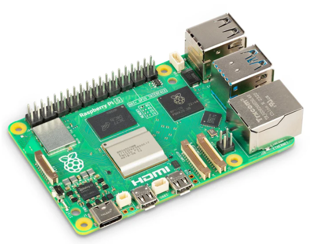
Raspberry Pi 5 2GB
The Raspberry Pi 5 2GB model represents a leap for...
| SKU: | 2648-SC1110-ND |
|---|---|
| Stock: | 116 |
| Cost: | $38.33 |
AKX00069
Arduino
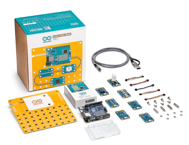
Arduino Plug and Make Kit
The Arduino Plug and Make Kit features the ...
| SKU: | 1050-AKX00069-ND |
|---|---|
| Stock: | 980 |
| Cost: | $66.97 |
300361-0011
Molex
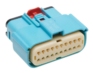
MX150 Mid-Voltage MatSealed Female Connector Assembly, Dual Row, 20 Circ...
| SKU: | 900-3003610011-ND |
|---|---|
| Stock: | 280 |
| Cost: | $2.37 |