
Op-amp opps in battery-powered IIoT applications
Op-amps have been around for decades, but Mouser Electronics’ Mark Patrick suggests some new potential applications where they constantly perform a measurement or signal conditioning function without significantly impacting battery life.
This article originally appeared in the Nov'22 magazine issue of Electronic Specifier Design – see ES's Magazine Archives for more featured publications.

An op-amp typically features a single-ended output and differential inverting and non-inverting inputs. Used as an open loop amplifier, its high gain characteristics create an output many thousands of times bigger than the potential difference between the inputs. Often used in a closed-loop configuration, negative feedback limits and controls the gain, with output voltage restricted by the supply rails levels (Figure 1).
Op-amp configurations include differential amplifiers, voltage followers, differentiators, or integrators. Functions typically include active filters, level shifters, buffering, signal conditioning, small-signal (AC/DC) amplification and function generator.
Op-amps in practice The input offset voltage is applied at the differential inputs to create a zero output voltage (Vio). Typical Vio values vary considerably, from a few tens of µV to hundreds of mV. Vio can represent a significate proportion when measuring very low input voltages, resulting in an erroneous output voltage.
Input bias current typically occurs due to leakage currents and varies according to the process technology. It can also result from the biasing components used around the inputs. Although an input bias current (Iib) may be tiny, typically pA or nA in magnitude, a noticeable voltage reduction may occur in high impedance input circuits such that it impacts the output.
Another key parameter to consider is gain-bandwidth product. This illustrates how the op-amp performs across a frequency range, typically exhibiting a gradual reduction in gain as frequency increases.
Bear in mind that an op-amp with rail-to-rail inputs can accommodate input voltages between +Vcc and -Vcc, while rail-to-rail outputs mean the op-amp output voltage can span +Vcc to -Vcc.
An op-amp’s slew rate determines how fast the output can change compared to the input signal. It is measured in mV/s as the output voltage swings from 10 to 90% of peak value. In high frequency applications, if the output cannot accommodate the rate of input changes, the signal integrity is compromised.
Further parameters to consider are input capacitance which can affect performance as the frequency of the input signals increase.
Noise levels
Like many components, op-amps have several noise sources capable of inducing noise on the output signal when no input is present. They include thermal noise and 1/f noise. Selecting a low-noise op-amp for high-gain and wide bandwidth use cases is recommended.
The impact of factors like input offset voltage varies with temperature and time; a zero-drift op-amp uses an input swapping or chopping approach to negate these influences.
Op-amps have much lower power specifications than other IC devices, with some as low as 900nA per input, which are excellent for battery-powered applications.
The ST TSZ121 series low input offset, precision, zero drift op-amp is available in various package configurations. The rail-to-rail input and output op-amp operates from a 1.8 to 5.5V DC supply, has a maximum power profile of 40µA (at 5V) and exhibits a typical offset voltage of 5µV (at 25°C). The op-amps (Figure 2) are suitable for portable, battery-powered applications, signal conditioning circuits and medical instrumentation equipment.

A precision 8mΩ shunt resistor is placed in series with the battery's load. A 100mA current passes through the shunt resistor, generating an 800µV voltage, which is applied to the differential inputs via two 10Ω resistors. The op-amp configuration has a gain of 1,000, so voltage would be 0.8V at the output. In practice, with an input offset voltage of 5µV, the actual voltage measured at the output will be 0.805V.
Another widespread use of op-amps is in active filter circuits. Figure 3 shows a circuit diagram of a bandpass filter with Analog Devices’ ADA4062 low power op-amp selected for the first stage. Components can be selected manually or using the Analog Design Filter Wizard. The ADA4062 has a typical slew rate of 3.3V/µs, a low input bias current of 50pA and an input offset voltage of 500 µV. It can operate off ±5 V to ± 15 V rails and has a typical power consumption of 165µA.


Featured products
MAX17793
Analog Devices Inc.
3V to 80V, 3A, High-Efficiency, Synchronous Step-Down DC-DC Converter
| SKU: | MAX17793 |
|---|---|
| Stock: | 9316 |
| Cost: | $3.64 |
MAX22516
Analog Devices Inc.
IO-Link Data Link Controller with Transceiver and Integrated DC-DC
| SKU: | MAX22516 |
|---|---|
| Stock: | 8000 |
| Cost: | $5.42 |
Product Spotlight
102991834
BeagleBoard

Single Board Computer (SBC), BeagleY-AI
AM67A BeagleY-AI Jacinto 7 AR...
| SKU: | 2820-102991834-ND |
|---|---|
| Stock: | 210 |
| Cost: | $56.24 |
SC1110
Raspberry Pi
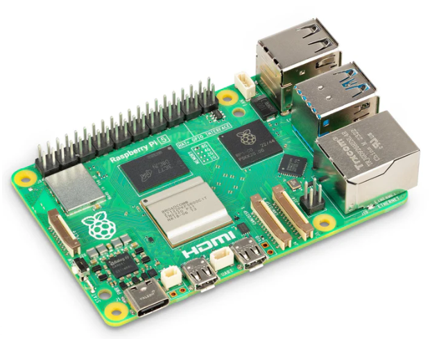
Raspberry Pi 5 2GB
The Raspberry Pi 5 2GB model represents a leap for...
| SKU: | 2648-SC1110-ND |
|---|---|
| Stock: | 0 |
| Cost: | $38.33 |
AKX00069
Arduino
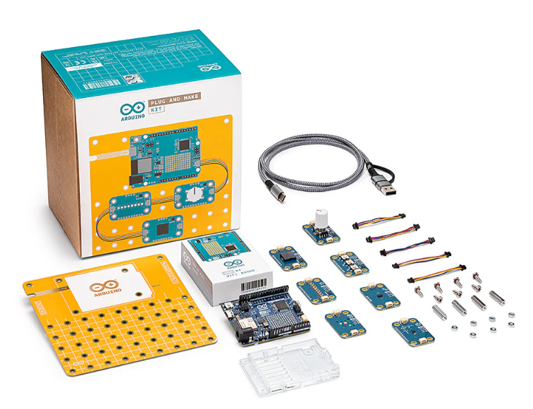
Arduino Plug and Make Kit
The Arduino Plug and Make Kit features the ...
| SKU: | |
|---|---|
| Stock: | 968 |
| Cost: | $66.97 |
300361-0011
Molex
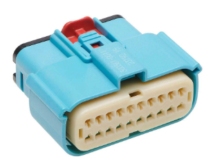
MX150 Mid-Voltage MatSealed Female Connector Assembly, Dual Row, 20 Circ...
| SKU: | |
|---|---|
| Stock: | 280 |
| Cost: | $2.51 |