
Design
Flexibility though design
John Canfield, Design Engineer with Linear Technology, takes an in depth look at expanding input capabilities and regulating seamlessly through automotive cold-crank and load-dump transients, in this article from ES Design magazine.
HandThe proliferation of electronic subsystems in automobiles has created demand for small size, high reliability power supplies that can operate under the stringent conditions presented by the automotive environment. Figure 1 shows a 5V automotive supply ideal for use in engine control units and other critical functions including safety, fuel system and drive train subsystems where processors must remain powered without glitch during even the most severe input voltage transients. This application uses a 2MHz switching frequency to minimise its footprint and eliminate interference with the AM broadcast band.

The VCC rail provides power to the internal circuitry of the LTC3115-1 (see below) including the power device gate drivers and is ordinarily powered from the input rail via an internal linear regulator. In this application, diode D1 bypasses the internal linear regulator and delivers power to the VCC rail directly from the regulated output to improve efficiency and output current capability. This is particularly advantageous in applications with higher switching frequencies, given that the increased gate drive current is provided more efficiently from the converter’s output rail than through the internal linear regulator. Figure 2 shows the efficiency of this application circuit with a 500mA load for input voltages from 3.3V to 40V.

Riding through line transients
Of commonly utilised power sources, the automotive supply rail presents one of the most challenging inputs to a power supply. Its nominal voltage varies from 10.6V to 15V depending on the state of charge of the battery, the ambient temperature and whether the alternator is charging or idle. In addition to the variability in its nominal voltage, the automotive power rail is also subject to a wide range of dynamic disturbances induced by changes in engine RPM, transitioning loads such as power windows, wipers and air conditioning, and inductive transients in the wiring harness.
However, the most extreme conditions occur during a load-dump transient which can produce voltages in excess of 120V for a duration of hundreds of milliseconds. A load-dump transient occurs when the alternator is charging the vehicle’s battery and an electrical open-circuit causes a momentary disconnection of the battery from the alternator. Until the voltage regulator can respond, the full alternator charging current is applied directly to the automotive power bus, raising its voltage to potentially dangerous levels. Such a transient could be caused through a physical disconnection of the battery by a mechanic working on the vehicle, but could also result from a faulty connection in the battery cable or corrosion at the battery terminals.
Automotive electronics must also be designed to survive a double-battery jump start, where they are subjected to 24V for extended durations as the vehicle is jump started using a series-connected second battery or from a commercial vehicle with a dual battery electrical system. An additional overvoltage condition on the automotive bus is caused by alternator voltage regulator failure and is often included in the battery of tests conducted by automotive electronics OEMs. Such a malfunction can result in full application of the alternator charge current to the battery and an overvoltage of approximately 18V for extended durations.
The automotive power rail is also polluted with short duration overvoltage transients due to rapid load changes produced by switching high power loads such as power doors, fans and cooling fan motors interacting with the significant inductance in the vehicle’s wiring harness.

In most vehicles a passive protection network consisting of a lowpass LC filter and transient voltage suppression (TVS) array is used as a first line of defence to clamp the peak excursions of the power bus. Typically, automotive electronics located downstream from the protection network must survive up to a 40V transient without damage. Critical systems must not only survive, but must also function seamlessly through such transients without interruption. Figure 3 illustrates the ability of the LTC3115-1 to maintain uninterrupted regulation of a 5V supply rail through a 13.8 to 40V momentary line transient with 1ms rise and fall times.
Cold-crank transients
High voltage transients are a problem on the automotive power bus, but perhaps the more challenging problem is undervoltage transients. The most severe of these is known as cold-crank, which occurs when the engine is initially started.
A typical cold-crank voltage waveform is shown in Figure 4. The initial low voltage plateau is the most extreme and is caused when the starter motor begins turning over the engine from a dead stop. During this phase, the vehicle’s bus voltage can fall below 4V. Colder temperatures exacerbate the situation since the higher viscosity of the engine oil results in a higher required torque from the starter motor. The first plateau is followed by a second somewhat higher voltage plateau, typically near half the nominal battery voltage, as the starter maintains the engine rotation. Once the engine starts, the battery recovers to its nominal voltage.

Safety devices and engine critical components such as the engine control unit and fuel injection system are required to remain operational throughout a cold-crank transient. As shown in Figure 4, the LTC3115-1’s buck-boost architecture enables it to maintain output regulation through even the most severe cold-crank transients by automatically and seamlessly switching to boost mode operation during the undervoltage event.
Cold-crank capability for automotive electronics has expanded in importance as cars now include automated fuel-saving, on-demand engine start/stop, whereby the vehicle’s engine is turned off during momentary vehicle stops at stoplights or in traffic. Vehicles equipped with on-demand starting are subjected to frequent cranking undervoltage events. As a result, auxiliary electrical components that previously had no need to function through the occasional cold-crank event in a traditional vehicle must now operate through such transients to eliminate any disturbance to infotainment, navigation, dashboard electronics and lighting systems.
The LTC3115-1 features a low noise forced PWM mode where both switch pins operate at constant frequency for all loads, producing a low noise spectrum, independent of operating conditions. The predictable spectrum and minimal subharmonic emissions help reduce interference and aid in compliance with strict automotive EMI standards.
The LTC3115-1 supports switching frequencies up to 2MHz so that the fundamental switching frequency component, and all of its harmonics, can be located above the AM frequency band to minimise interference with radio reception. Figure 5 shows the spectral emission of the LTC3115-1 over the AM band for the automotive application circuit of Figure 1 operating at no load and with a 500mA load. In both cases the entire range of frequencies within the AM broadcast band is free from any significant spectral emission.

Multiple power sources
To increase flexibility and enhance the user’s experience, many portable electronic devices are being designed to work from various power sources. These power sources can vary widely in voltage, especially when accounting for connector and cable drops.
Under USB 3.0, the nominal supplied voltage is 5V ±5%, but a fully compliant powered device must be able to operate down to 4V when accounting for allowable cable and connector voltage drops. In addition, a downstream USB power rail is permitted to drop as low as 3.67V under transient conditions such as when additional devices are plugged into the host or powered hub.
The newly approved USB PD (power delivery) specification allows for higher power delivery over USB with support for supply voltages up to 20V. Firewire ports deliver an unregulated power rail with a voltage that varies over a wide range, typically 9V to 26V depending on the class of the power provider.
The ubiquitous wall adapter remains perhaps the most common source of power for portable devices. A typical wall adapter is simply a transformer followed by a bridge rectifier, offering no active regulation. That task is left to the end device to avoid the effects of cable drop. Unregulated wall adapters are designed to provide rated current at the specified typical output voltage. Being unregulated, the output voltage is a load line function, increasing substantially at lighter loads and decreasing under heavy load. In addition, the AC line voltage is permitted to vary between 105V and 125V, adding an additional 10% variability in the unregulated wall adapter’s output. It is not uncommon for a 12V unregulated wall adapter to produce an output voltage of 17V or greater at light load.
The LTC3115-1 operates directly from all of these portable power sources as well as from a variety of battery chemistries including lithium (single cell or series connected), sealed lead acid, three or more series alkaline cells and even a bank of supercapacitors for backup applications. Multiple power sources can be combined through a Schottky diode-OR circuit.

For higher efficiency, the LTC3115-1 can be combined with an ideal diode PowerPath controller to provide automatic switchover between multiple power sources using the low voltage drop of a power P-channel MOSFET to replace the Schottky diode. Figure 6 shows how the LTC3115-1 can be combined with the LTC4412HV to obtain a dual input — single lithium and unregulated wall adapter — 5V supply. In this case, a series PMOS is used on the lower voltage lithium input while an inexpensive Schottky diode is used on the higher voltage input where its voltage drop is insignificant. The overall efficiency of this supply including the converter and PowerPath is given in Figure 7 for each power input.
The flexibility and high efficiency of the LTC3115-1 make it suitable for many next generation automotive electronics and portable devices, especially those operated from multiple power sources. Its internal power switches and programmable switching frequency minimise the power solution footprint, supporting the increasing demand for miniaturisation of electronic devices in the portable and automotive arenas.
About the LTC3115-1:
The LTC3115-1 provides uninterrupted operation through load dump transients and even the harshest cold-crank conditions. Its programmable switching frequency optimises efficiency and supports operation at 2MHz to ensure that switching noise and harmonics are located above the AM broadcast band. It employs a proprietary low noise PWM control algorithm that minimises electromagnetic emissions over all operating conditions even during transitions between the step-up and step-down modes of operation and over the full range of load current. An internal phase-locked loop allows switching edges to be synchronised with an external clock for further control of EMI in noise-sensitive applications.
An accurate RUN pin provides a programmable input undervoltage lockout threshold with independent control of hysteresis. By consuming only 30µA of quiescent current in Burst Mode operation and 3µA in shutdown, the LTC3115-1 reduces standby current drain on automobile batteries to negligible levels.
The LTC3115-1 is also well suited for handheld devices, which are required to interface to an expanding array of power sources. While it was once common for portable devices to be powered by a dedicated AC adapter or a single power source, many must now be compatible with a variety of inputs including automotive, USB, Firewire and unregulated wall adapters. Next generation military radios and support electronics are an extreme example, requiring the capability to operate from all available power sources for emergency use and to minimise the number of battery varieties carried in the field.

Featured products

MAX17793
Analog Devices Inc.

3V to 80V, 3A, High-Efficiency, Synchronous Step-Down DC-DC Converter
| SKU: | MAX17793 |
|---|---|
| Stock: | 9316 |
| Cost: | $3.64 |

MAX22516
Analog Devices Inc.

IO-Link Data Link Controller with Transceiver and Integrated DC-DC
| SKU: | MAX22516 |
|---|---|
| Stock: | 8000 |
| Cost: | $5.42 |
Product Spotlight
102991834
BeagleBoard

Single Board Computer (SBC), BeagleY-AI
AM67A BeagleY-AI Jacinto 7 AR...
| SKU: | 2820-102991834-ND |
|---|---|
| Stock: | 208 |
| Cost: | $56.24 |
SC1110
Raspberry Pi

Raspberry Pi 5 2GB
The Raspberry Pi 5 2GB model represents a leap for...
| SKU: | 2648-SC1110-ND |
|---|---|
| Stock: | 0 |
| Cost: | $38.33 |
AKX00069
Arduino
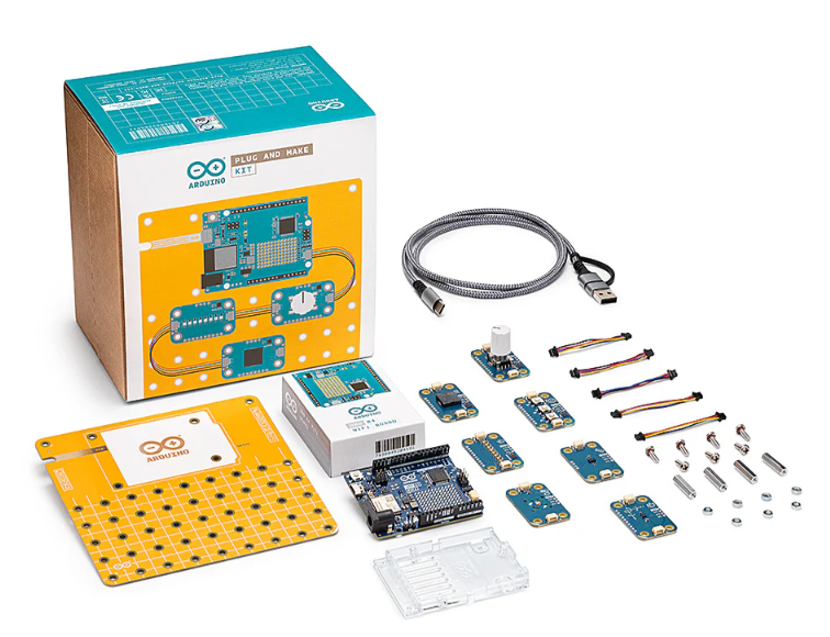
Arduino Plug and Make Kit
The Arduino Plug and Make Kit features the ...
| SKU: | |
|---|---|
| Stock: | 968 |
| Cost: | $66.97 |
300361-0011
Molex

MX150 Mid-Voltage MatSealed Female Connector Assembly, Dual Row, 20 Circ...
| SKU: | |
|---|---|
| Stock: | 280 |
| Cost: | $2.51 |