"Fast time-to-market" - inspiring or meaningless?
Is the phrase "Fast time-to-market" on the side of an MCU starter-kit confidence-inspiring, or virtually meaningless now there is so much more to think about?
By Steve Norman, Core Marketing Manager, Industrial and Communications Business Group, Renesas Electronics Europe.
Today’s market conditions dictate that when choosing a MCU there is a lot of ancillary aspects that the engineer must consider, such as availability of reference or production software and hardware, safety certification, a clear GUI, expert support and developments from prime third party partners. Most of all, though, there is the application to think about. The job of the MCU vendor today is to make the designer successful as this makes the supplier successful. As an example, let’s assume a company wants to develop a ventilation system managing air flow while eliminating vibration through low speed operation. The system will operate from 200 to 4000RPM at 800W, 400V, 1Nm torque and use a brushless AC motor driven by a sensorless three-phase inverter. Companies tendering must provide a working demonstrator in four weeks and three companies tender: Company A assigned their team of three engineers to the task; Companies B and C assigned a single engineer to produce the demonstrator.
All three companies needed to perform the same development and motor tuning operations in order to produce a working system: extract the motor parameters; prepare the 3-phase software to drive the motor; tune the closed loop filters for speed and torque to the application specification, and develop the MCU based hardware system for the demonstration. Both Companies A and B took a ‘conventional’ approach to preparing the demonstration: adapting existing hardware to support the design; adapting existing sensorless 3-phase software; extracting the motor parameters using an RLC meter; tuning the current Pi filter using software and external oscilloscope to initially be able to turn the motor, and many man-hours to tune the software and Pi filters to get the necessary speed and torque responses. While Company A delivered a working prototype on time it was over budget. Company B was late and was not considered, but company C delivered a working demonstrator on time and to budget. So the question is what did Company C do differently?

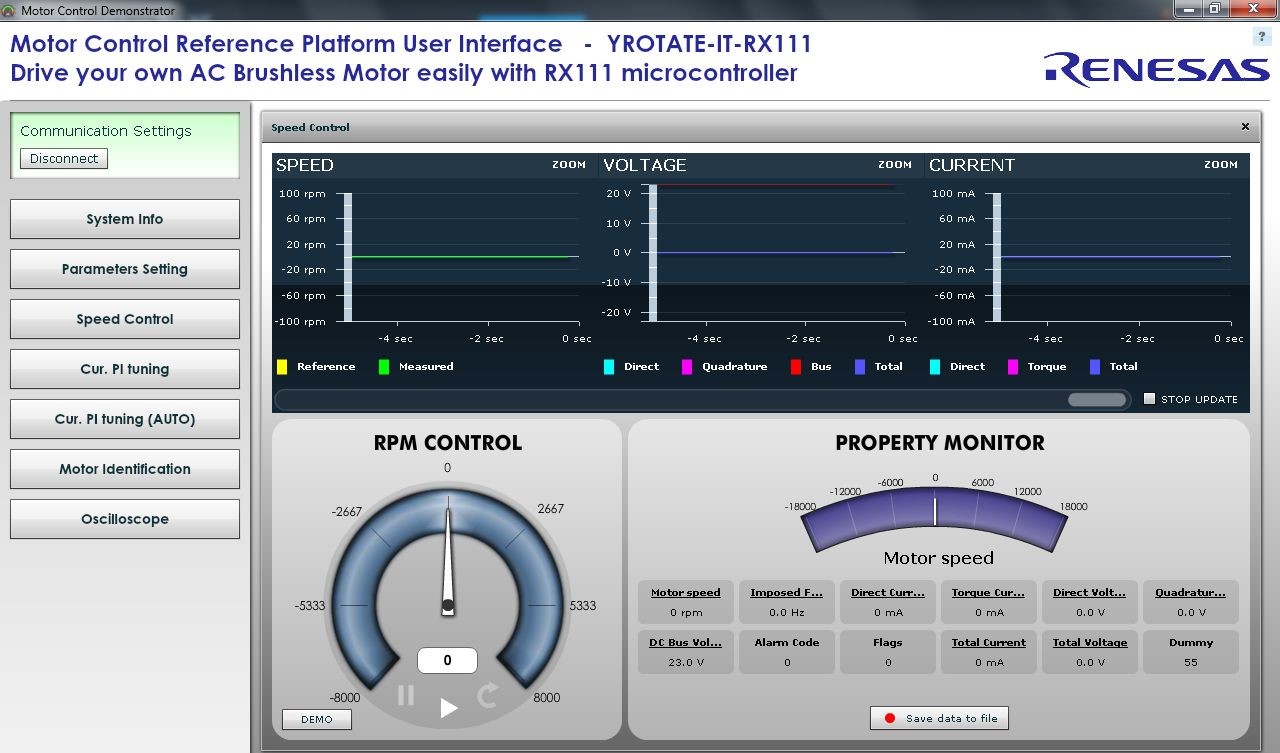
Figure 1 - Starter-kit control board and GUI
A different approach
Company C took a different approach as they had little existing collateral available, so went looking for a complete kit in order to meet the development timescales and budget. They selected a motor control kit which came complete with professionally developed sensorless three-phase royalty-free reference software, a hardware reference platform including full schematics, bill of materials, Gerber layout files and the option of a fully compatible external high voltage inverter unit. All the software is fully VDE certified and comes complete with a development environment and graphical interface. More than you might expect to find in a low cost motor control package. It’s a good start, although for the demo there is no hardware design necessary; only simple configuration of the MCU control board for the external inverter.
The sensorless software system is ready to go, but still needs to be adapted to work with the motor (i.e. parameter extraction and tuning). The engineer is familiar with motor control but has limited experience in tuning motors, which is one of the key factors in choosing the Renesas kit; the software includes some advanced motor tuning functions such as automatic parameter identification for most three-phase brushless permanent magnet motors and auto-tuning software for Pi filter (current) design coefficients, all embedded in the MCU source code and designed to operate under the control of the PC GUI without the need for any extra hardware. Even a digital oscilloscope is included in the GUI so no need for any external equipment apart from a mains plug.
Once the engineer had installed all the necessary software and GUI, and the kit was tested with the demonstration motor supplied, he was ready to start development using the customer’s motor. It was decided that as the motor was required to run down to 200RPM that the demo would use a three-shunt system to limit the effects of the low signal levels and provide more stable operation at low speed, thus no changes were necessary for the inverter.

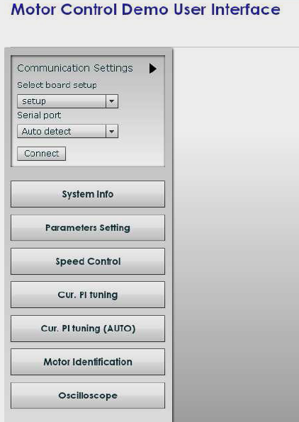
Figure 2 - PC GUI tuning
Once the GUI has connected with the control board software the parameter tuning functions ‘Current Pi tuning’ and ‘Motor Identification’ (Figure 2) are available to start the process of configuring the software to drive the motor together with the tab to open a digital oscilloscope. A few parameters need to modified and added in Parameter settings window (Figure 3) before starting the auto tuning process.
Once complete clicking on ‘Current PI tuning (AUTO)’ automatically calculates the proportional and integral coefficients for the current Pi control filter in just a few seconds. The results are stored in the software. At this point the dynamic response based on these coefficients can be checked manually with the oscilloscope, adjusting and retuning the parameters if necessary.
Next the motor Stator resistance, Stator and Synchronous Inductance and Permanent Magnet flux need to be measured. Again a simple click of the ‘Motor Identification’ button is all that is required. Once complete the system is ready to run the motor. The system can then be run turning the motor so that system tuning can be completed and the system tested with the motor under load conditions. This usually takes a while and is down to the experience of the designer. The GUI still allows full control, monitoring and adjustment of the system and motor parameters during operation, utilising the oscilloscope function to analyse the waveforms as necessary. Using the GUI and the embedded measurement software took just a few minutes to complete, from GUI launch to a running sensorless vector-controlled motor. While the completed development took a little longer, this allowed the engineer ample time to get a working demonstration to the customer on time, to specification and within budget in order to win the business for his company.

Figure 3 - GUI parameter settings
This study is based on the use of the ‘Rotate-it’ Motor Control Solution Kits available for the RX100, RX200 and RX600 families of 32-bit MCU, which form part of the next-generation solutions from Renesas Electronics, embracing the philosophy of more than just time to market, by providing professional software and hardware reference platforms combined with unique features to provide designers with the tools to work effectively, efficiently and successfully in a variety of market areas, with a low entry cost.
The way forward
Continuing with the theme of providing solutions rather than just hardware and a few basic peripheral driver examples, Renesas Electronics recently introduced the RZ/A family, featuring a 400MHz ARM Cortex-A9 core. Combined with FPU and encryption functions, the family includes a rich peripheral set including communications interfaces for Ethernet, CAN, IEBUS and USB together with advanced graphics such as Image Rendering, JPEG codec, NTSC/PAL processing YUV/RGB conversion, audio processing IPs for SCUX, CDROM decoding and sound generation, plus large 10MB embedded SRAM to improve system, video and audio processing performance. When combined with the leading software ecosystem, this family is suited to next-gen HMI applications. With so many choices when it comes to the software ecosystem, it is a difficult choice of which to use and even more so if looking to compare those of interest, but that’s not how next-gen HMI development should work. A single solution kit uniquely supporting solutions such as IS2T JVM, TES GUIliani, Segger emWIN, Altia Design and Express Logic GUIX, now exists to support such applications, so the designer can chose the preferred software and start designing quickly saving time and cost.
Developers of complex communication technology, such as narrowband OFDM power line systems, face a different set of problems, not least the requirement to support many power line standards. For example, supporting multiple rollouts of smart meters based on different protocols in different countries that use different frequency bands and specifications. A flexible PLC modem solution is available based on a highly integrated narrowband modem with MAC controller, high performance digital signal processor for physical layer implementation, an embedded analogue front end with adaptive gain controlled amplifier and an embedded AES128 hardware security engine. The solution is combined with certified software for standards such as PRIME and G3, giving a leading power line solution meeting today’s market requirements.
Certified software can be a key factor in a successful design, saving the designer time and cost. For certification of end products, testing can be a huge proportion of time and cost. If software is provided that is certified to the appropriate standard it means the designer spends more time on developing the application code. This philosophy is being applied to new kits in development such as Wireless Meter Bus, Smart Analog for IO-Link, multi-protocol Industrial Ethernet and smart LED lighting.


